Hose kink resistanct testing device

Active Publication Date: 2016-01-07
TEKNOR APEX
View PDF3 Cites 7 Cited by
  • Summary
  • Abstract
  • Description
  • Claims
  • Application Information

AI Technical Summary

Benefits of technology

This invention aims to create a device that can measure the decrease in fluid flow caused by twisting a hose in a way that reduces the amount of fluid inside it. The technical effect is an improved way to measure the reduction of fluid flow in a hose.

Problems solved by technology

The apparatus aims to subject the hose during its testing operation to substantially the treatment as it is likely to get when in actual use, and thereby develop any weaknesses that will otherwise appear after the hose has gone in use.

Method used


Image

  • Hose kink resistanct testing device
  • Hose kink resistanct testing device
  • Hose kink resistanct testing device

Examples


Embodiment Construction

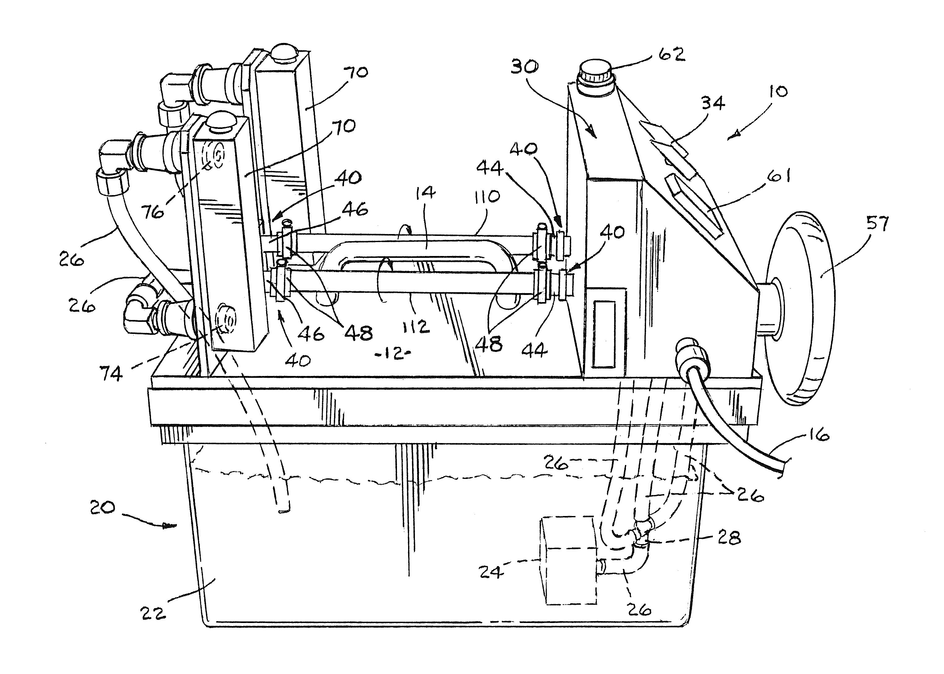
[0023]The hose kink resistance testing device provides visual feedback as well as informative data regarding the flow rate of a fluid through the hose, preferably water in one embodiment, as well as degrees of hose twist, pressure source backpressure, and information regarding torque. When two or more hoses are tested simultaneously, an observer can visually assess the kink resistance thereof in addition to being able to monitor and / or record other data produced during testing. Advantageously, the testing device of the present invention can be utilized to simulate relatively normal testing conditions that a hose would be subjected to, as well as non-typical or extreme testing conditions.

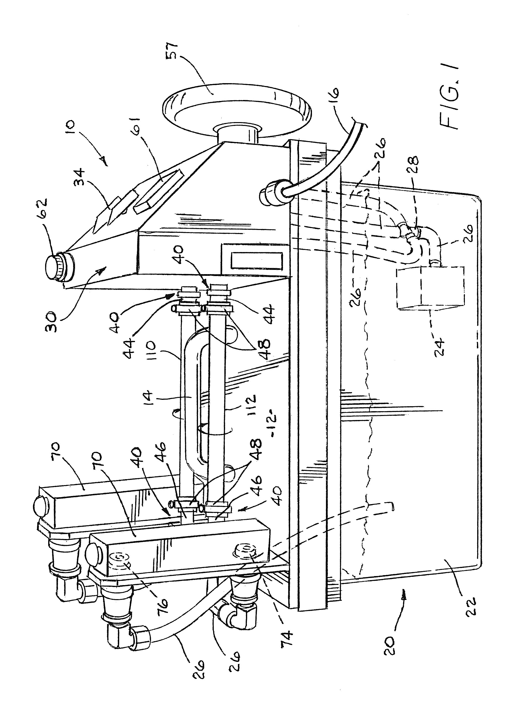
[0024]Referring now to the drawings wherein like reference numbers refer to like parts throughout the several views, a hose testing device 10 is illustrated therein. FIG. 1 illustrates base 20 of the device 10 that includes a fluid reservoir 22 that is adapted to hold a fluid that can be circulated t...


PUM


Abstract

A device and methods for testing and quantifying the kink resistance of a hose. The device has the ability to simultaneously test a plurality of hoses at equal amounts of twist or torque while water or other fluid is pumped through the hoses. The device can monitor one or more of the flow rate of fluid through a hose, fluid backpressure from a pressure source, torque and degrees of hose twist.

Description

FIELD OF THE INVENTION[0001]The present invention relates to a device and methods for testing and quantifying the kink resistance of a hose. The device has the ability to simultaneously test a plurality of hoses at equal amounts of twist or torque while water or other fluid is pumped through the hoses. The device can monitor one or more of the flow rate of fluid through a hose, fluid backpressure from a pressure source, torque and degrees of hose twist.BACKGROUND OF THE INVENTION[0002]It is desirable for hose manufacturers to test hoses, in particular garden hoses, utilizing the same or similar treatment as the hoses are likely to receive when in actual use. As such, various devices have been proposed in the art.[0003]U.S. Pat. No. 1,512,063 relates to a device for testing short lengths of hose, and particularly hose which is subjected to a considerable fluid pressure or heat and pressure when in use, such as air-brake and steam hose for railway trains. One object is to provide a me...

Claims


Application Information

Patent Timeline
IPC IPC(8): G01N3/26G01F1/00G01L3/00
CPCG01N3/26G01L3/00G01F1/00G01M99/00G01N3/12
Inventor CHAPMAN, TIMOTHY, L.
Owner TEKNOR APEX
Why Eureka
Try Eureka