Sensing Device with a Glare Shield

Active Publication Date: 2016-01-28
IR TEC INT
View PDF0 Cites 0 Cited by
  • Summary
  • Abstract
  • Description
  • Claims
  • Application Information

AI Technical Summary

Benefits of technology

The present invention provides a sensing device with a glare shield to prevent incorrect determination of ambient luminance and misoperation when the infrared sensor is bundled with a lighting device in operation. The technical effect is that the glare shield prevents glare emitted from adjacent light sources from affecting the infrared sensor, resulting in accurate and reliable data.

Problems solved by technology

However, when in use, conventional infrared sensing devices are susceptible to glare from lighting devices in the nearby or in a range of lighting and thus easily misjudge environmental luminance to incorrectly turn on or turn off lighting devices corresponding to the conventional infrared sensing devices.

Method used


Image

  • Sensing Device with a Glare Shield
  • Sensing Device with a Glare Shield
  • Sensing Device with a Glare Shield

Examples


first embodiment

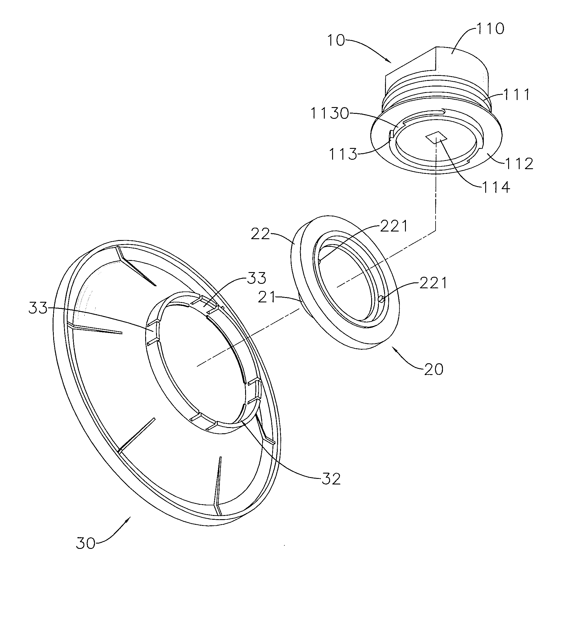
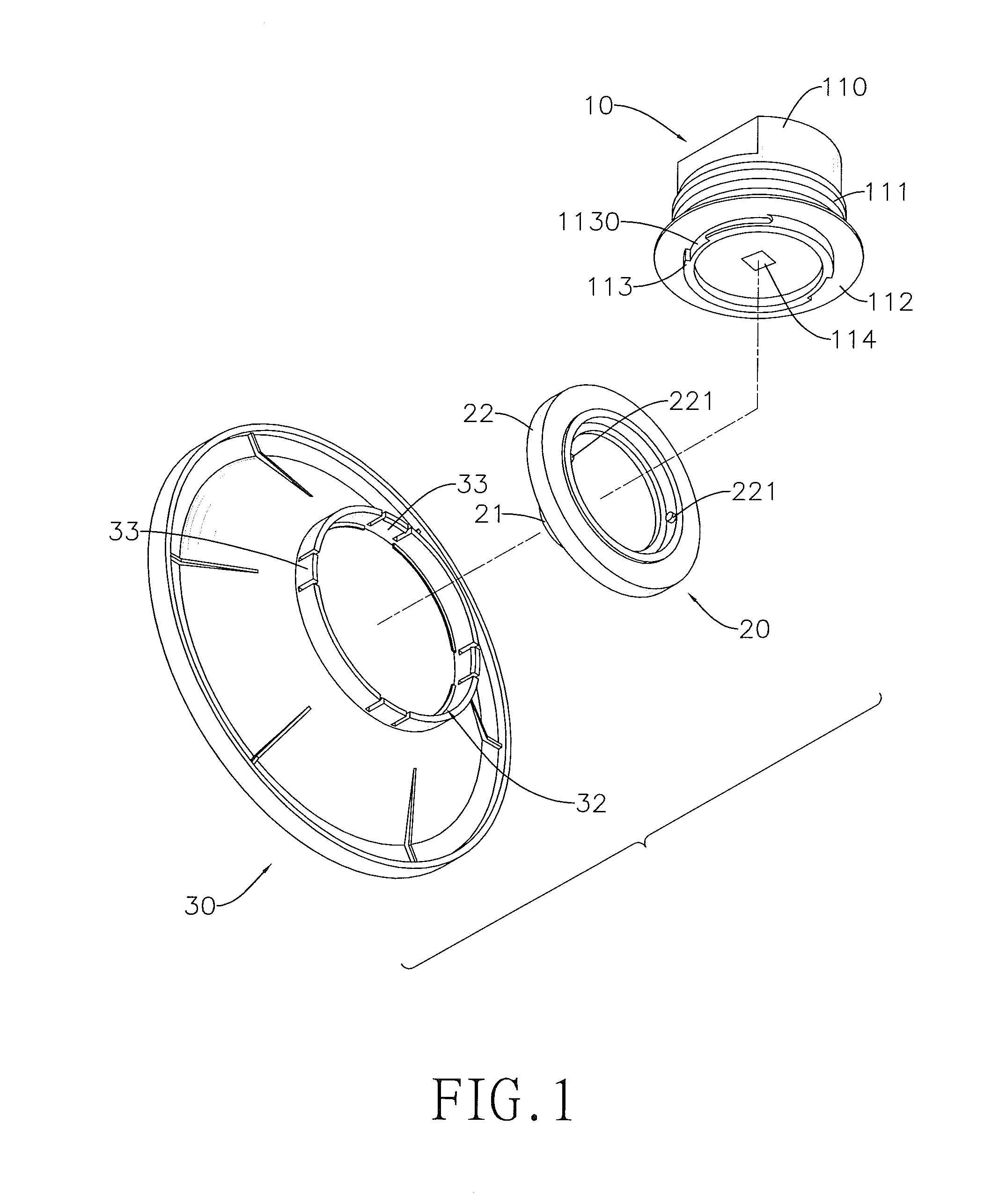
[0021]With reference to FIGS. 1 and 2, a sensing device with a glare shield in accordance with the present invention has an infrared sensor and a glare shield 30.

[0022]The infrared sensor has a body 10 and a lens hood 20. The body 10 has a light-receiving side, a mounting portion 110, an outer threaded portion 111, a positioning disc 112, an annular protrusion 113, and an infrared sensing element 114.

[0023]In the present embodiment, the mounting portion 110 is cylindrical. The outer threaded portion 111 is formed on an outer periphery of the mounting portion 110. The positioning disc 113 is formed on a bottom surface of the mounting portion 110 with an edge of the positioning disc 113 protruding beyond the outer periphery of the mounting portion 110. The annular protrusion 113 is formed on a bottom of the positioning disc 112, and has multiple L-shaped recesses 1130 formed in an outer wall of the annular protrusion 113 and spaced apart by gaps. The infrared sensing element 114 is mo...

second embodiment

[0028]With reference to FIG. 4, a sensing device with a glare shield in accordance with the present invention has an infrared sensor, a glare shield 70 and a mounting ring 80. The infrared sensor has a body 50 and a lens hood 60. Differences between the present embodiment and the foregoing embodiment are described as follows.

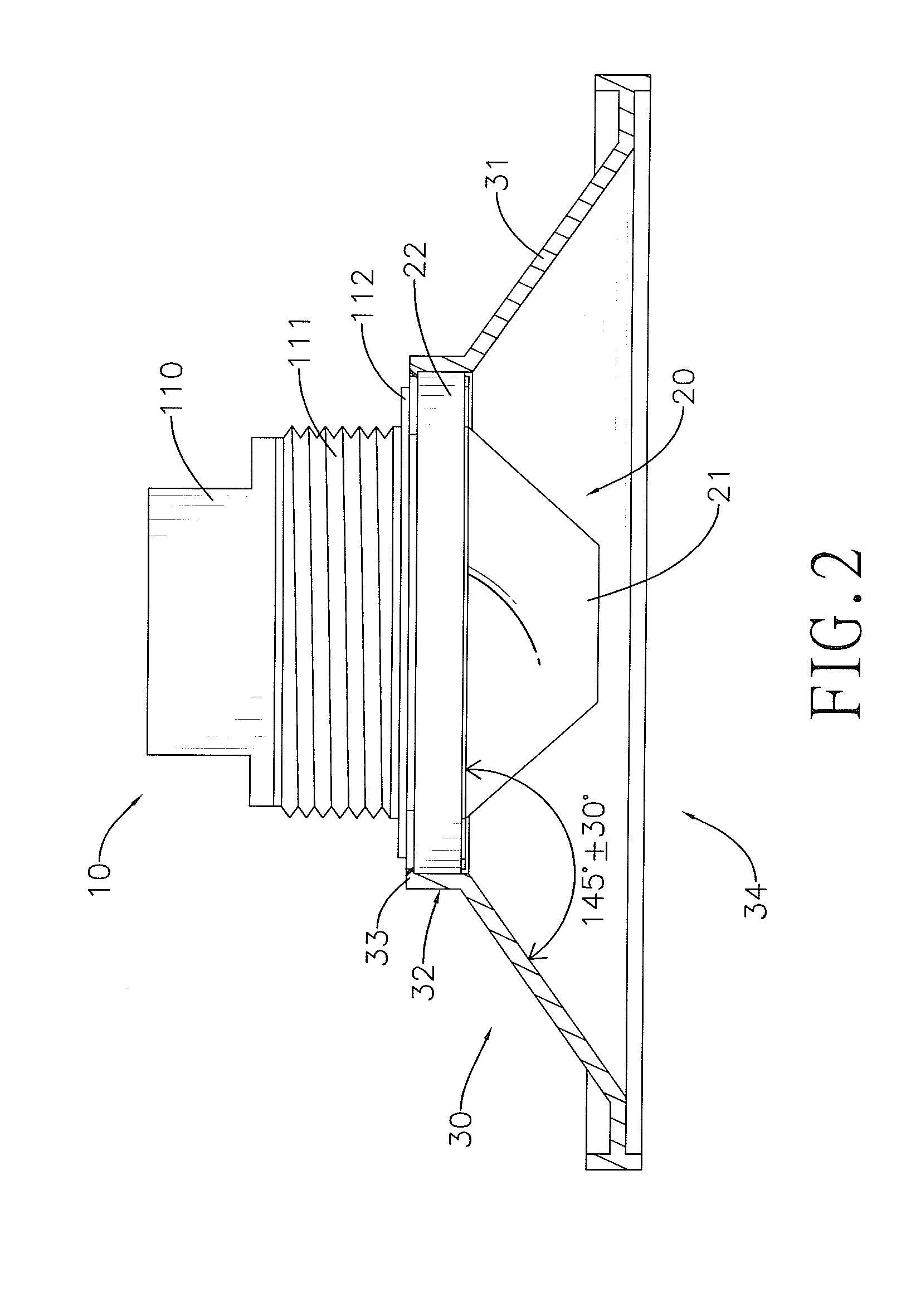
[0029]The glare shield 70 has a conical portion 71 and a bottom opening 72. The conical portion 71 has two open ends. The two open ends of the conical portion 71 differ from each other in diameter. The lens hood 60 is integrally formed on an inner wall of the open end of the conical portion 72 with a smaller diameter. An included angle between an inner side of the conical portion 71 and the lens hood 60 is in a range of 145°±30°. The bottom opening 72 is defined at the open end of the conical portion 71 with a larger diameter.

[0030]The body 50 has a mounting portion 51 and an outer threaded portion 52. The outer threaded portion 52 is formed on a periphery of th...


PUM


Abstract

A sensing device with a glare shield has an infrared sensor and a glare shield. The infrared sensor has a body and a lens hood. The lens hood is mounted around an outer periphery of the body. The glare shield is conical, is detachably mounted around the lens hood of the infrared sensor, and extends in a direction away from the body of the infrared sensor. The glare shield prevents the infrared sensor from being affected by glare emitted from adjacent lighting devices. Accordingly, the sensing device avoids incorrect judgment of environmental luminance caused by lighting devices nearby and therefore generates less misoperation, so that the goal of being more power-saving can be achieved.

Description

BACKGROUND OF THE INVENTION[0001]1. Field of the Invention[0002]The present invention relates to a sensing device with a glare shield, and more particularly to an infrared sensing device using a glare shield against glare from neighboring light sources.[0003]2. Description of the Related Art[0004]Sensing devices can be classified info many different types, such as temperature-sensing device, humidity-sensing device, infrared-sensing device and the like, based on sensing techniques of the sensing devices. The infrared-sensing devices can be bundled with lighting devices in operation and mounted at venues like hallway, stairway, garage and so on. For example, an infrared sensing device detects infrared rays emitted from an intruder and drives a bundled lighting device to turn on upon detection of the intruder's entry into a detection range thereof, and drives the lighting device to turn off when the intruder is out of the detection range, thereby providing powers-saving and anti-theft...

Claims


Application Information

Patent Timeline
IPC IPC(8): G01J5/08G01J5/04
CPCG01J5/08G01J5/04G01J5/0803G01J1/0403G01J5/06G01J1/0214
Inventor HUANG, WEN-I
Owner IR TEC INT
Why Eureka
Try Eureka