Gaze detection apparatus, gaze detection method, and non-transitory computer readable medium

a detection apparatus and gaze technology, applied in the field of line-of-sight (gaze) detection apparatus, can solve the problems of low accuracy of error determination, inability to estimate the accuracy of line-of-sight detection, and inability to determine the error at high accuracy. the effect of high accuracy

Pending Publication Date: 2022-06-23
CANON KK
View PDF2 Cites 0 Cited by
  • Summary
  • Abstract
  • Description
  • Claims
  • Application Information

AI Technical Summary

Benefits of technology

[0004]The present invention provides a technique that allows to perform an error determination of line-of-sight (gaze) detection at high accuracy.

Problems solved by technology

Then if it is determined that the line-of-sight detection cannot be performed, the cause of the line-of-sight detection impossibility is estimated.
In this method, however, an incorrect detection of the line-of-sight cannot be determined as an error at high accuracy.
If the accuracy of the error determination is low, improper processing, based on an incorrectly detected line-of-sight, is performed at high frequency, for example.

Method used


Image

  • Gaze detection apparatus, gaze detection method, and non-transitory computer readable medium
  • Gaze detection apparatus, gaze detection method, and non-transitory computer readable medium
  • Gaze detection apparatus, gaze detection method, and non-transitory computer readable medium

Examples


embodiment 1

[0026]Embodiment 1 of the present invention will be described with reference to the accompanying drawings.

[0027]Description on Configuration

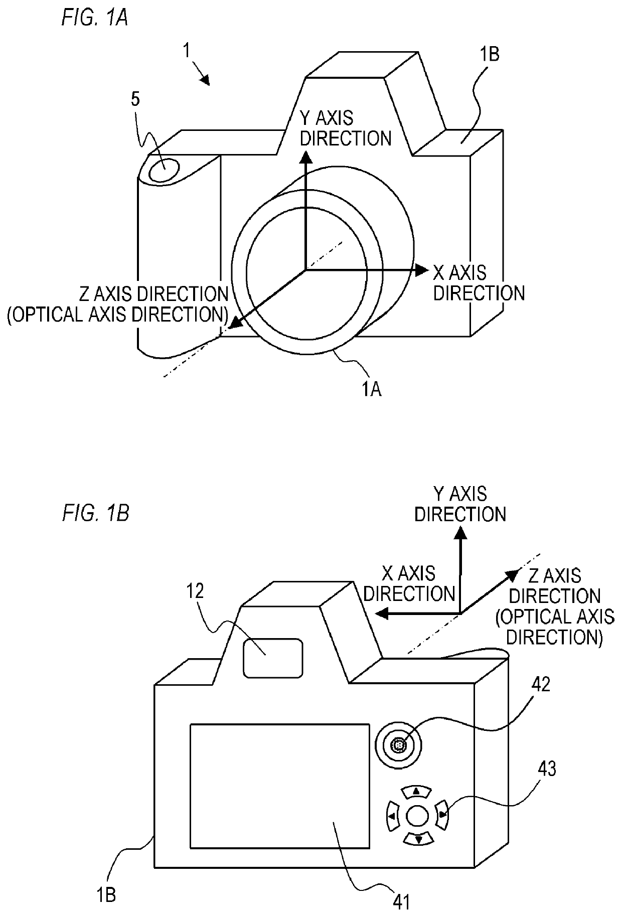
[0028]FIGS. 1A and 1B are external views of a camera 1 (digital still camera; lens interchangeable camera) according to Embodiment 1. FIG. 1A is a front perspective view and FIG. 1B is a rear perspective view. As illustrated in FIG. 1A, the camera 1 has a photographing lens unit 1A and a camera body 1B. A release button 5, which is an operation member to receive photographing operation from the user (photographer), is disposed on the camera body 1B. As illustrated in FIG. 1B, an eye piece 12 (eye piece optical system) for the user to look into a later mentioned display device 10 (display panel) included in the camera body 1B, is disposed on the rear face of the camera body 1B. The eye piece optical system may include a plurality of lenses. Operation members 41 to 43, to receive various operations from the user, are also disposed on the rear face...

embodiment 2

[0114]Embodiment 2 of the present invention will be described next. In the following, description on the aspects (e.g. configuration, processing) the same as Embodiment 1 is omitted, and aspects that are different from Embodiment 1 will be described. In Embodiment 1, an example of performing the error determination during camera operation was described. In Embodiment 2, an example of performing the error determination in a state where an index to be viewed is displayed on the display device 10 will be described. The intended use of the index is not especially limited, but in Embodiment 2, a case of using the index for the calibration operation will be described.

[0115]As described om Embodiment 1, the calibration operation is performed by emphasizing a plurality of indices located at different positions on the display device 10 before capturing an image, and having the user view these indices. For example, as illustrated n FIG. 4C, the indices are displayed at five locations on the d...


PUM


Abstract

A gaze detection apparatus according to the present invention, includes at least one memory and at least one processor which function as: a detection unit configured to detect a gaze of an eye that views a display surface, based on an eye image obtained by capturing the eye; and a determination unit configured to determine whether the detection of the gaze is in error, based on a current eye image and a past eye image.

Description

BACKGROUND OF THE INVENTIONField of the Invention[0001]The present invention relates to a line-of-sight (gaze) detection apparatus, and an imaging apparatus equipped with the line-of-sight detection apparatus.Description of the Related Art[0002]Recently cameras are becoming more and more automated and intelligent. Japanese Patent Application Publication No. 2004-8323 discloses a technique that allows a user to recognize an intended object and perform focus control, based on information on a viewpoint (line-of-sight (gaze) position) of the user who looks into a finder without manually inputting the object position. Further, Japanese Patent Application Publication No. H07-289517 discloses a technique in which reliability of a line-of-sight detection result is determined using a captured eye image, and it is determined whether the line-of-sight detection can be performed or not based on the reliability. Then if it is determined that the line-of-sight detection cannot be performed, the ...

Claims


Application Information

Patent Timeline
Patent Type & Authority Applications(United States)
IPC IPC(8): G03B13/02G06F3/01H04N5/232
CPCG03B13/02G03B2213/025H04N5/23219G06F3/013H04N23/54H04N23/50H04N23/55H04N23/611G03B13/10
Inventor TANAKA, SHU
Owner CANON KK
Why Eureka
Try Eureka