Bracket for bridging member for metal stud wall

Active Publication Date: 2016-03-10
BAILEY METAL PROD
View PDF11 Cites 8 Cited by
  • Summary
  • Abstract
  • Description
  • Claims
  • Application Information

AI Technical Summary

Benefits of technology

The invention provides a bracket for attaching bridging members to a thermal stud. The bracket has a C-shaped design with parallel flanges connected by a central web with openings in the web of the stud. The openings have flanges that extend perpendicularly from the edges of the opening into the interior of the stud. The bracket has a leg for overlying and a means to properly locate a bridging member centrally within the stud wall, as well as a centrally located tab to position properly against an edge of the opening within the web of the stud. The bracket's base has flanges that extend perpendicularly from the base at either end to engage and attach with the flanges of the stud.

Problems solved by technology

One drawback of metal studs is the thermal conductivity which the metal provides as compared to wood studs.
This is particularly an issue in colder climates where the metal studs are utilized in an exterior wall such that the metal stud can conduct colder temperatures through the wall and into the interior of the space.

Method used


Image

  • Bracket for bridging member for metal stud wall
  • Bracket for bridging member for metal stud wall
  • Bracket for bridging member for metal stud wall

Examples


Embodiment Construction

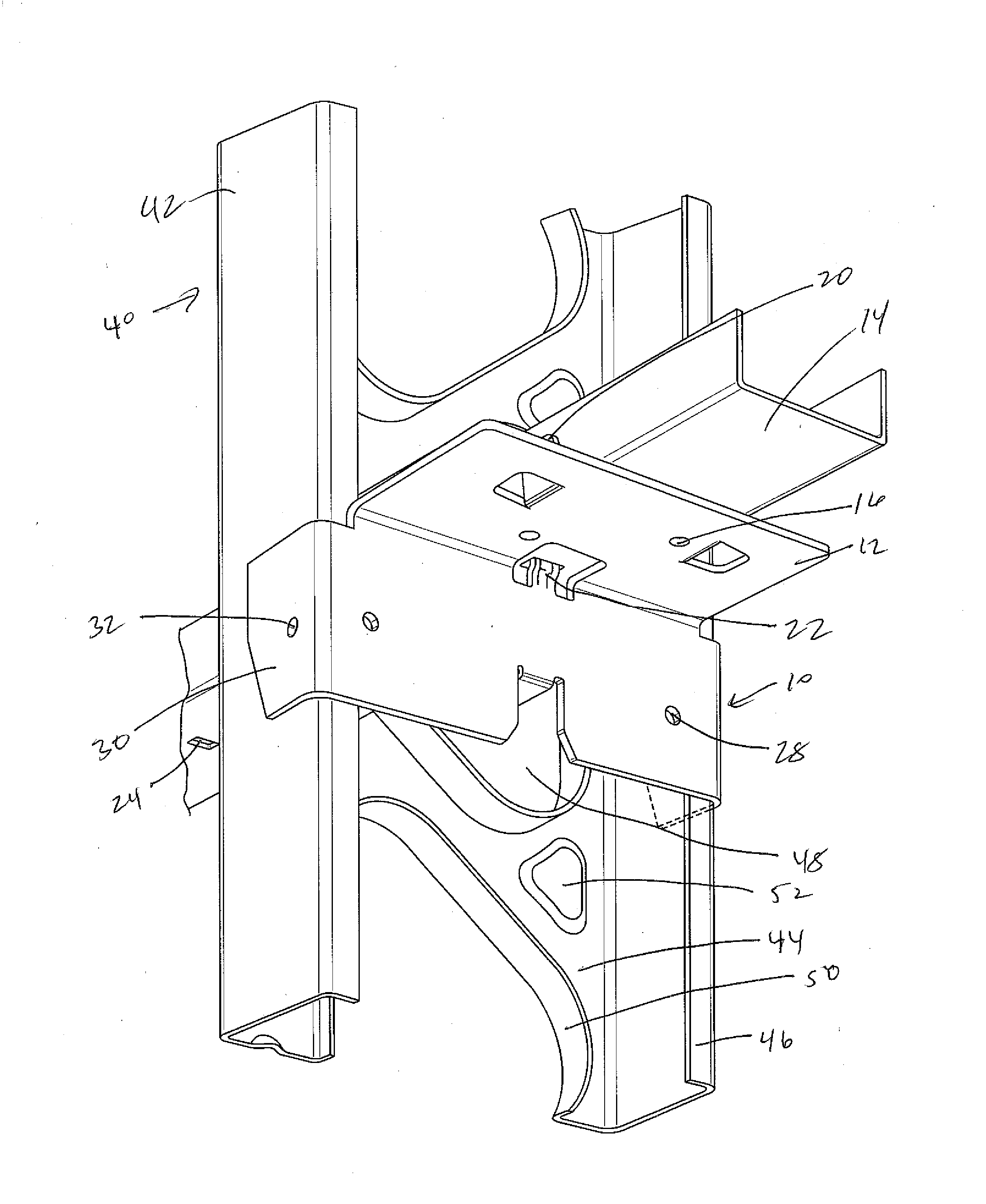
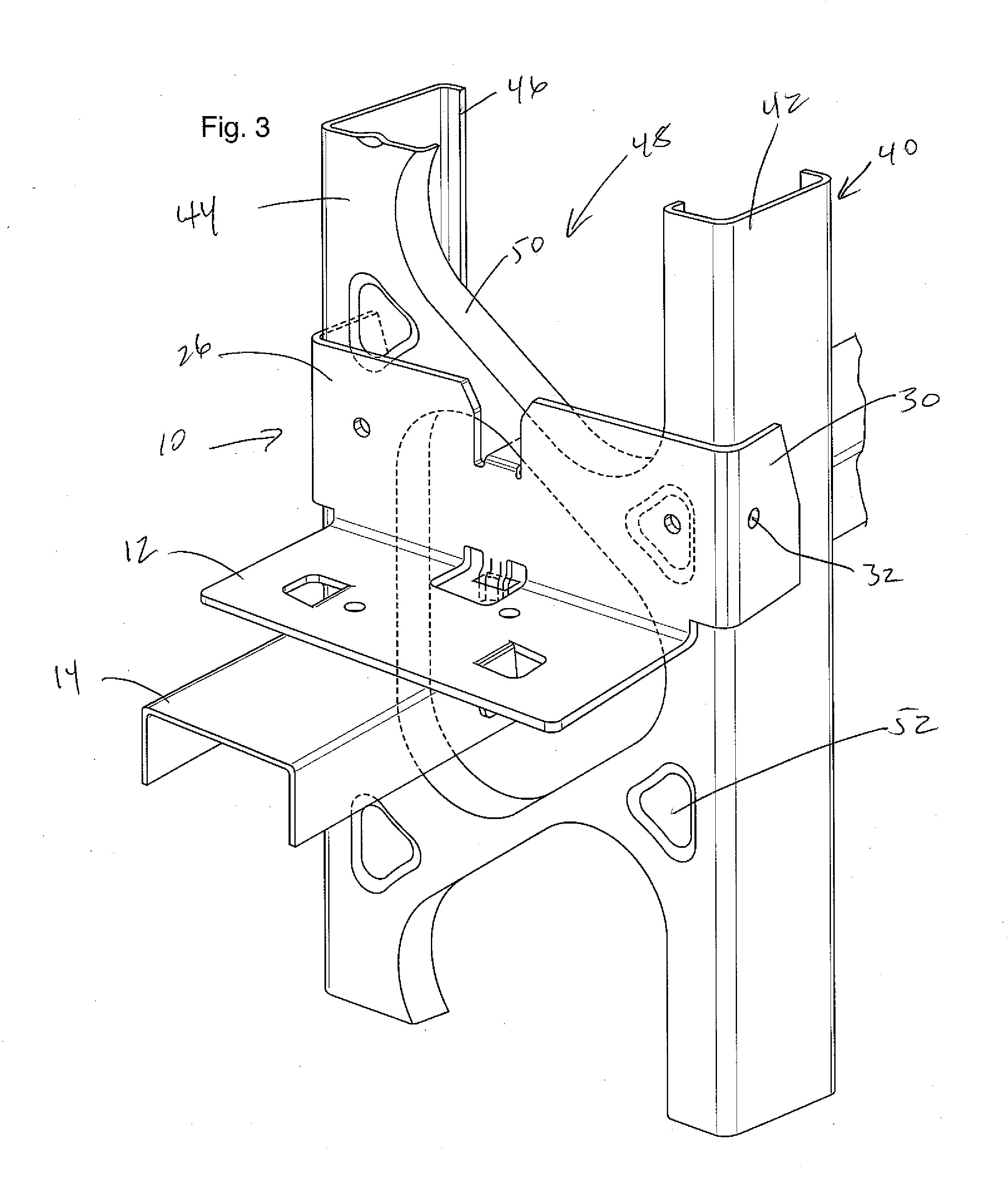
[0016]The bracket of the present invention is for use with thermal studs such as those illustrated in Canadian Patent 1,324,872 or 2,404,320. Such thermal studs typically are metal studs being generally C-shaped with spaced apart parallel flanges extending the length of the stud with the flanges being interconnected by a central web. In order to provide for the thermal break, the central web is provided with a plurality of openings which typically are generally triangular in shape. In order to provide for stiffening of the web, internally turned flanges are provided at the edges of the openings in the web the flanges extending into the interior of the stud as defined by the web and parallel spaced apart flanges. These features are shown in FIG. 3 as set out below.

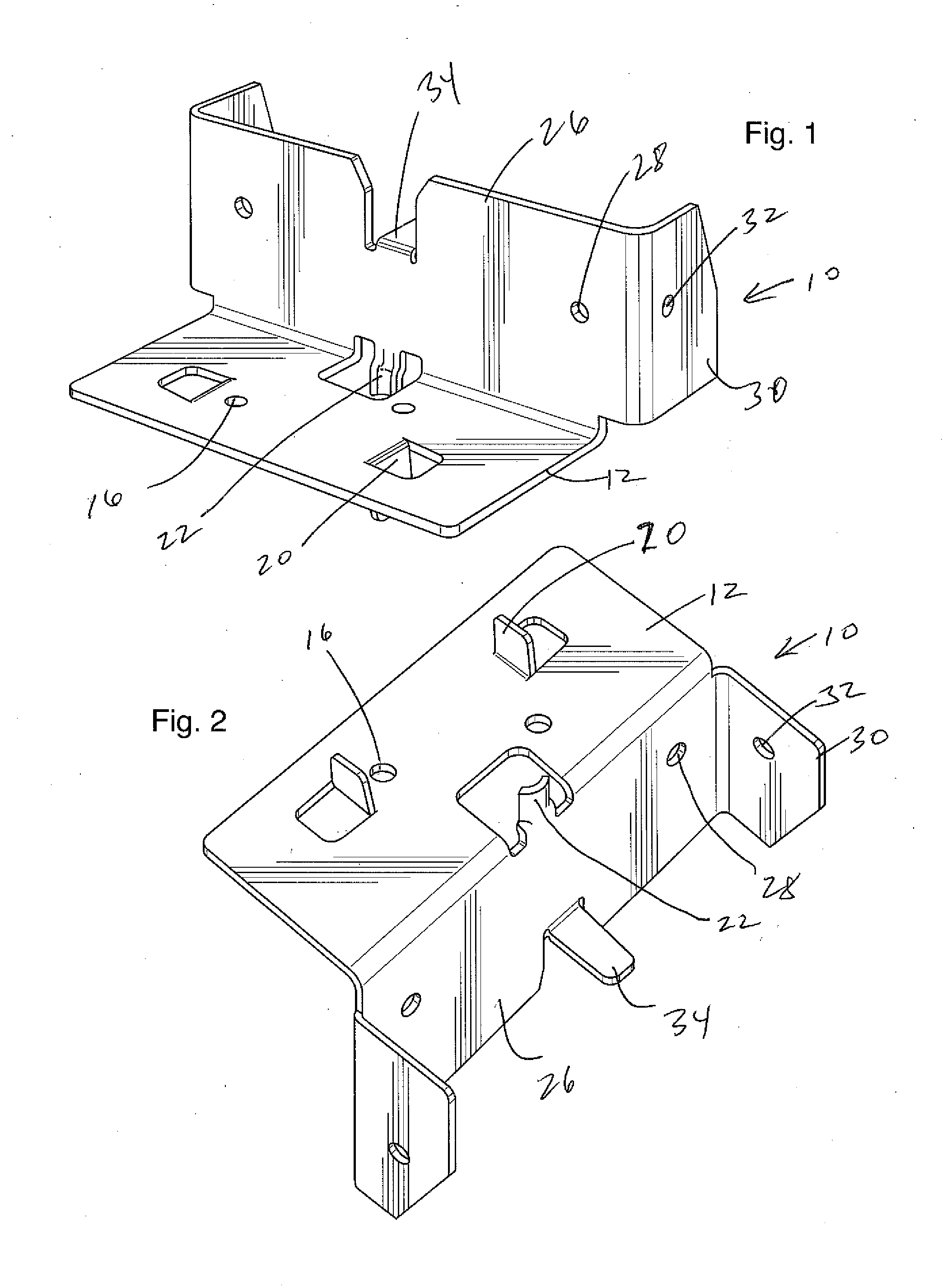
[0017]A preferred embodiment of the bracket of the present invention is illustrated in the drawings generally indicated by the numeral 10. The bracket 10 has a leg 12 which projects outwardly from the bracket to allow for a...


PUM


Abstract

A bracket for attaching bridging members to a thermal stud being generally C-shaped with parallel spaced apart flanges connected by a central web having opening in the web of the stud which spans the majority of the width of the web and where the openings are provided with flanges extending perpendicularly from the edges of the opening into the interior of the stud. The bracket is a generally L-shaped bracket having a leg with a means to properly locate a bridging member centrally within the bracket and the stud wall and a base for overlying the web of the stud. The base has a width approximately the same as the stud and preferably has flanges extending perpendicularly from the base at either end thereof to engage and be able to attach to the flanges of the stud. The base is also provided with a centrally located tab extending perpendicularly from the base to allow the bracket to be properly positioned within the web of the stud.

Description

FIELD OF THE INVENTION[0001]The present invention relates to a bracket for attaching bridging members to the studs of a metal stud wall. In particular, the present invention relates to a bracket which is utilized to attach bridging members to studs having enlarged openings for thermal break to provide for the proper support of the bridging members for the studs in the stud wall.BACKGROUND OF THE INVENTION[0002]Metal studs for use in constructing partition walls are becoming more prevalent. The metal studs of a generally C-shaped cross-section are utilized in a manner similar to wooden studs for constructing partition walls. Metal studs are typically arranged vertically and tied together at the top and bottom by U-shaped channel members which act as top and bottom plates for the stud wall. Stud walls which are subjected to wind and / or axial loads such as is found if the stud wall forms the exterior wall or as a load bearing wall require lateral support to provide resistance to rotati...

Claims


Application Information

Patent Timeline
IPC IPC(8): E04B2/62E04B2/72E04B2/76E04B2/78
CPCE04B2/62E04B2/762E04B2/789E04B2/761E04B2/721E04B2/763E04C3/09E04C2003/0473
Inventor RICE, JOHN
Owner BAILEY METAL PROD
Why Eureka
Try Eureka