Wheel cylinder adjuster

Active Publication Date: 2016-03-17
CHEN SHU HUI
View PDF0 Cites 4 Cited by
  • Summary
  • Abstract
  • Description
  • Claims
  • Application Information

AI Technical Summary

Benefits of technology

The purpose of this invention is to create an adjuster that can work with different sizes of wheel cylinders. This allows for easier and more convenient maintenance and repair of vehicles.

Problems solved by technology

The weight of the two sets of the wrenches 10, 11 and the multiple disks 12 is so heavy that the user is difficult to carry the tool box easily.
The size of the tool box is big and occupies spaces.

Method used


Image

  • Wheel cylinder adjuster
  • Wheel cylinder adjuster
  • Wheel cylinder adjuster

Examples


Embodiment Construction

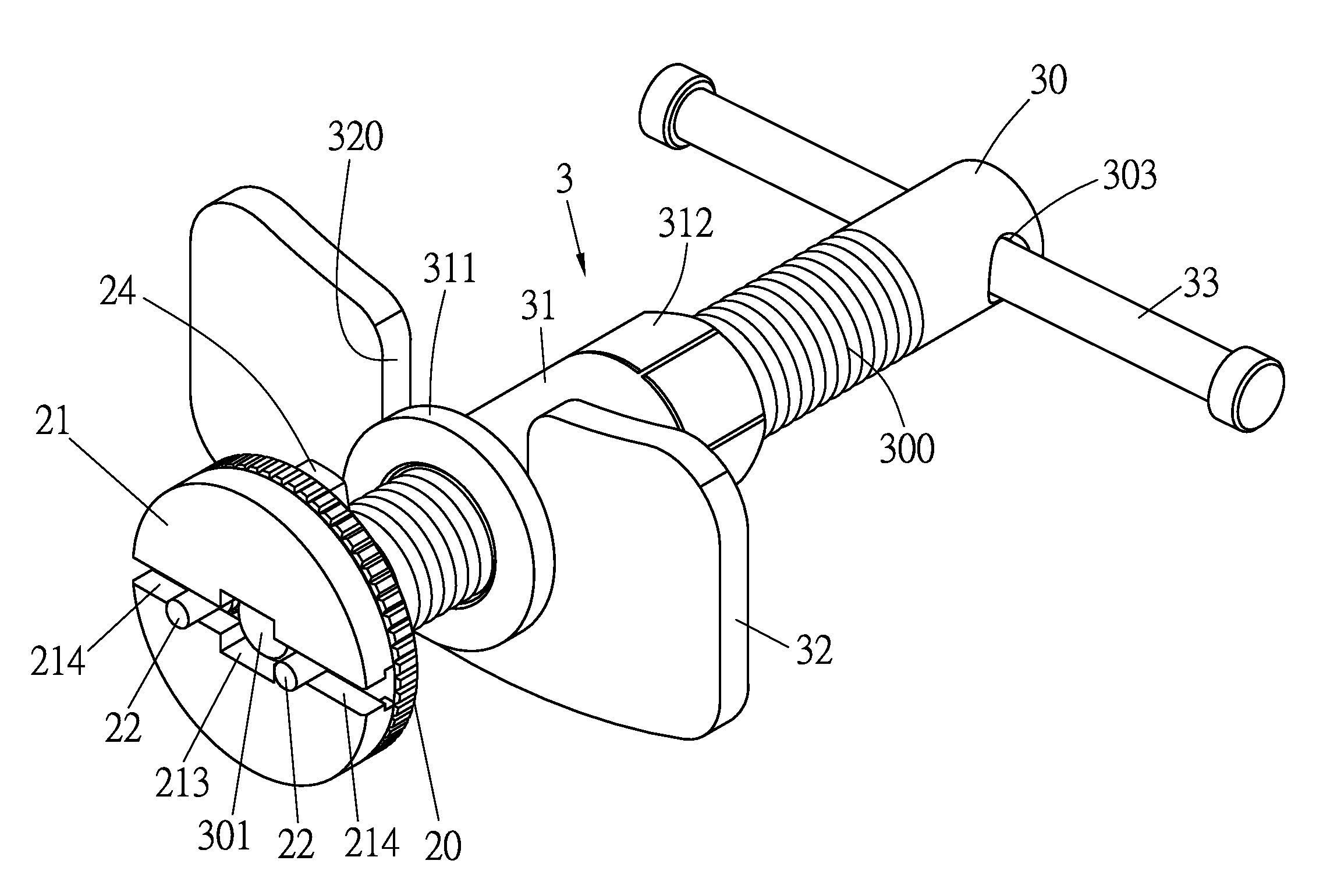
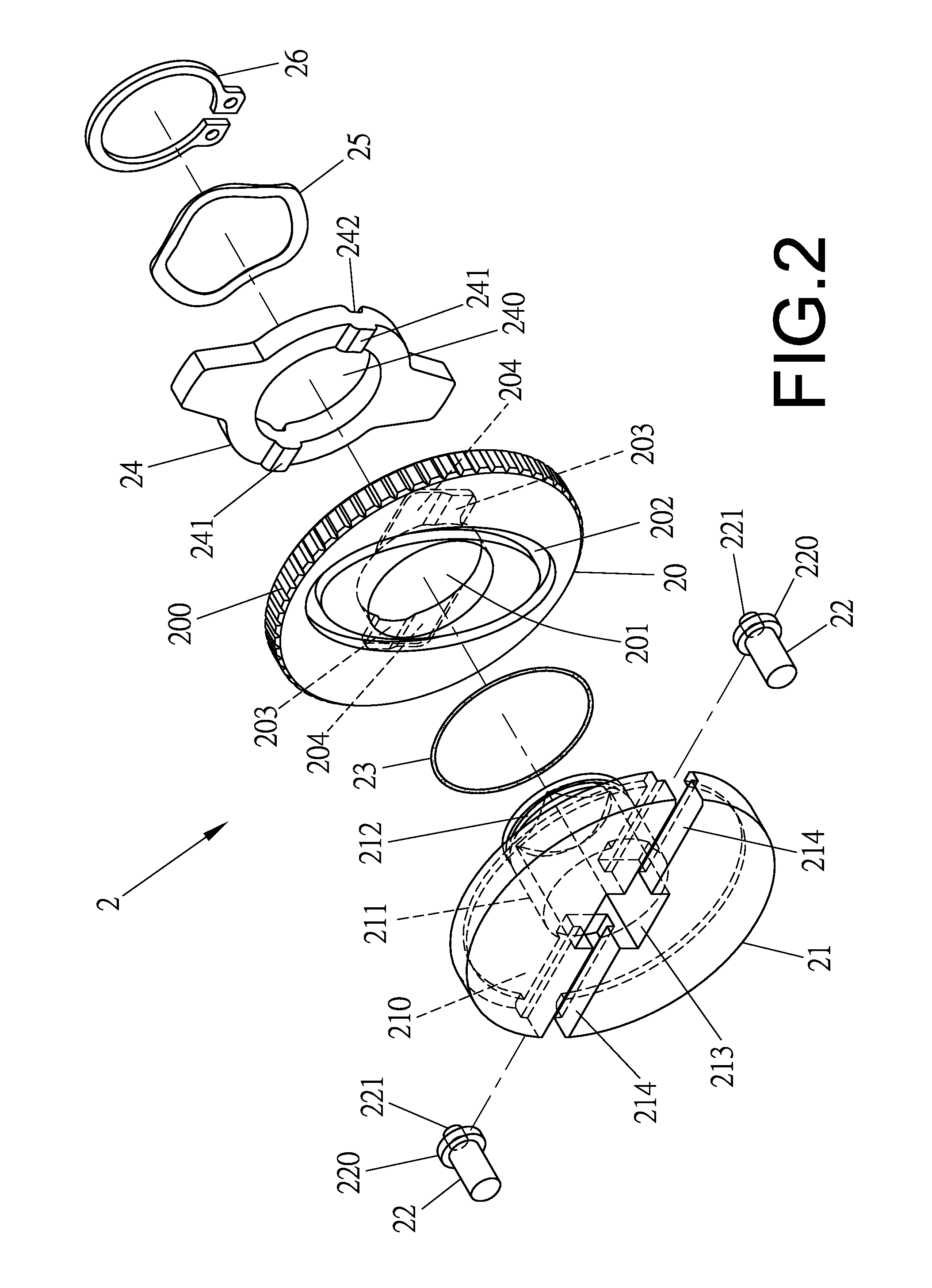
[0027]Referring to FIGS. 2 to 10, the adjuster of the present invention comprises a rotary unit 2 as shown in FIGS. 2 and 3, and a driving unit 3 as shown in FIG. 4. The rotary unit 2 is able to be connected with wheel cylinders of different sizes and comprises a rotary disk 20, a fixing member 21 two positioning members 22, a resilient ring 23, a restriction member 24 and a clip 26. The rotary disk 20 has an anti-slip surface 200 defined in the outside thereof and a through hole 201 is defied centrally through the rotary disk 20. A guide groove 202 is designed in a shape containing two semi-ovals and defined in the first side of the rotary disk 20. Two recesses 203 are defined in the second side of the rotary disk 20 and located diametrically relative to the through hole 201. Each recess 203 has a contact face 204 on one of two insides of the recess 203. The fixing member 21 is connected to the first side of the rotary disk 20 and has a recessed area 210 defined in one side thereof...


PUM


Abstract

A wheel cylinder adjuster includes a rotary unit and a driving unit connected with the rotary unit. The rotary unit includes a rotary disk, a fixing member, two positioning members, a resilient ring, a restriction member and a clip. The rotary disk has a guide groove designed in a shape containing two semi-ovals. Two stepped slots are defined through the fixing member and the positioning members extend through the two stepped slots. Each positioning member has a guide tip which is located in the guide groove. The resilient ring is mounted to the positioning members and the tubular portion. The rotary disk is rotated and the guide tips of the positioning members more in the stepped slots so as to adjust the distance between the positioning members so as to be operated to different sizes of the wheel cylinders.

Description

BACKGROUND OF THE INVENTION[0001]1. Fields of the Invention[0002]The present invention relates to a wheel cylinder adjuster, and more particularly, to an adjuster for different sizes of wheel cylinders.[0003]2. Descriptions of Related Art[0004]The conventional a wheel cylinder adjuster generally comprises a disk that is connected axially to the cylinder and a wrench that is connected to the disk. The disk has a hollow tubular portion extending from a center thereof and the size of the tubular portion is matched with the port of the valve. Two pivotal holes are located diametrically of the tubular portion. A positioning hole is defied in an outside of the tubular portion so that a positioning rod is inserted into the positioning hole. The wrench has a driving member at the distal end thereof, and a recessed area is defined in the driving member. A magnet is located in the recessed area. Two protrusions extend from the outer periphery of the recessed area so as to be pivotably connect...

Claims


Application Information

Patent Timeline
IPC IPC(8): F16D65/00
CPCF16D65/0043B25B27/00Y10T29/53683B25B27/0035B60T17/221
Inventor CHEN, SHU-HUI
Owner CHEN SHU HUI
Why Eureka
Try Eureka