Exercise Machine Carriage Handle System

a technology for carrying handles and exercise machines, applied in the field of carriage handles of exercise machines, can solve the problems of limiting the types and number of exercises, not ergonomically designed features, and not providing for exercisers using the apparatus

Active Publication Date: 2016-04-07
LAGREE TECH INC
View PDF1 Cites 77 Cited by
  • Summary
  • Abstract
  • Description
  • Claims
  • Application Information

AI Technical Summary

Benefits of technology

[0016]Provided herein is an exercise machine which includes a frame having a track, a carriage movably connected to the track, a bias member connected between the frame and the carriage, a first handle connected to the carriage near the first side,

Problems solved by technology

Sliding the carriage away from the first end of the apparatus to which one or more spring resistance means are attached creates a workload against which fitness exercises can be beneficially performed.
These features are not ergonomically designed for exerciser engagement unless the exerciser is mounted substantially or completely upon the Pilates apparatus.
One problem with traditional Pilates apparatuses is that they do not provide for exercisers using the apparatus when positioned adjacent to, and therefore not mounted upon the apparatus.
Although

Method used


Image

  • Exercise Machine Carriage Handle System
  • Exercise Machine Carriage Handle System
  • Exercise Machine Carriage Handle System

Examples


Embodiment Construction

A. Overview.

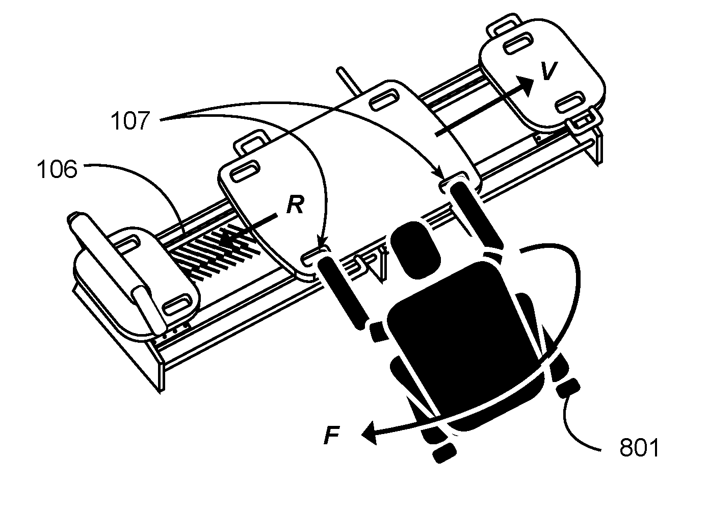
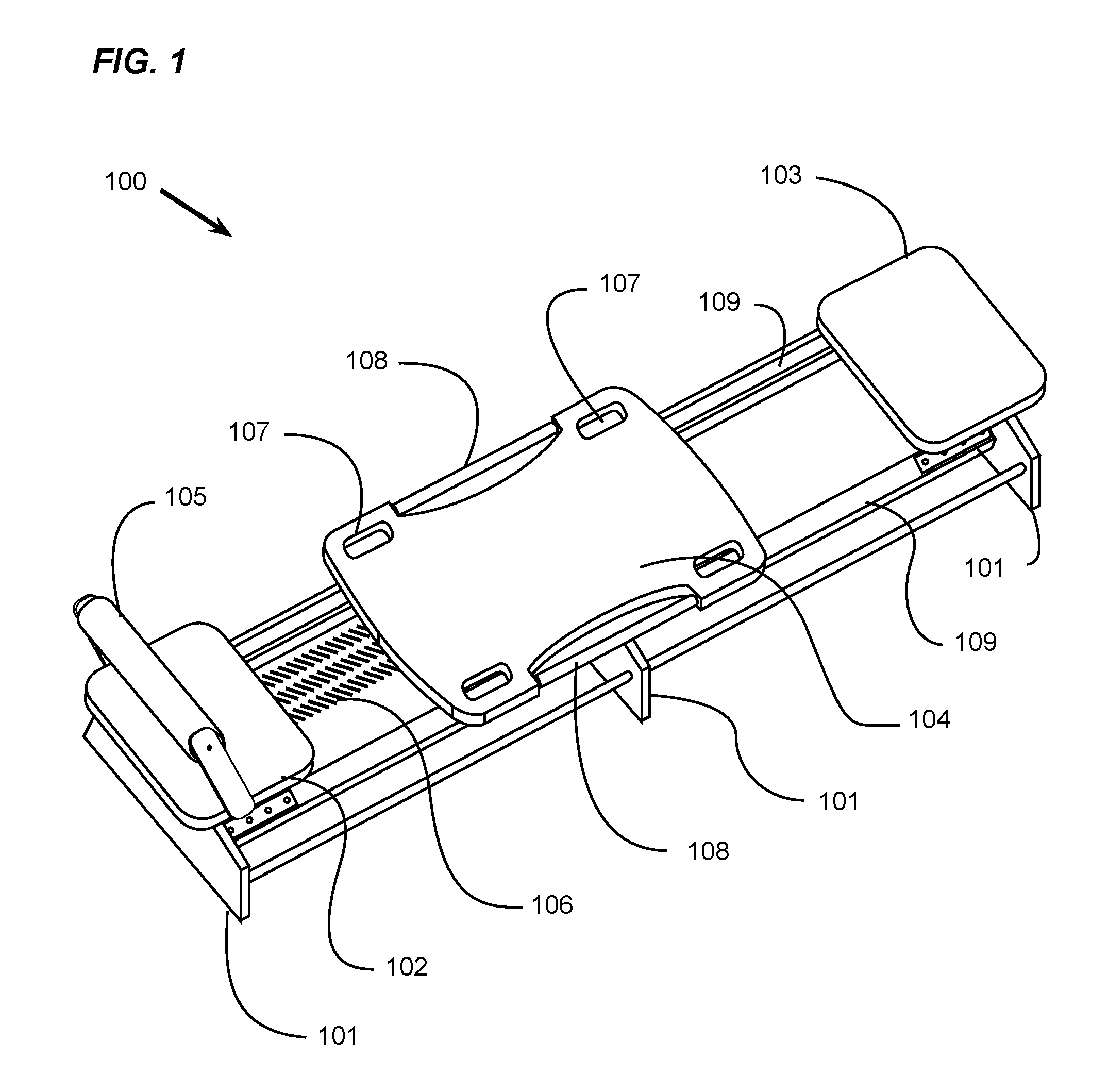
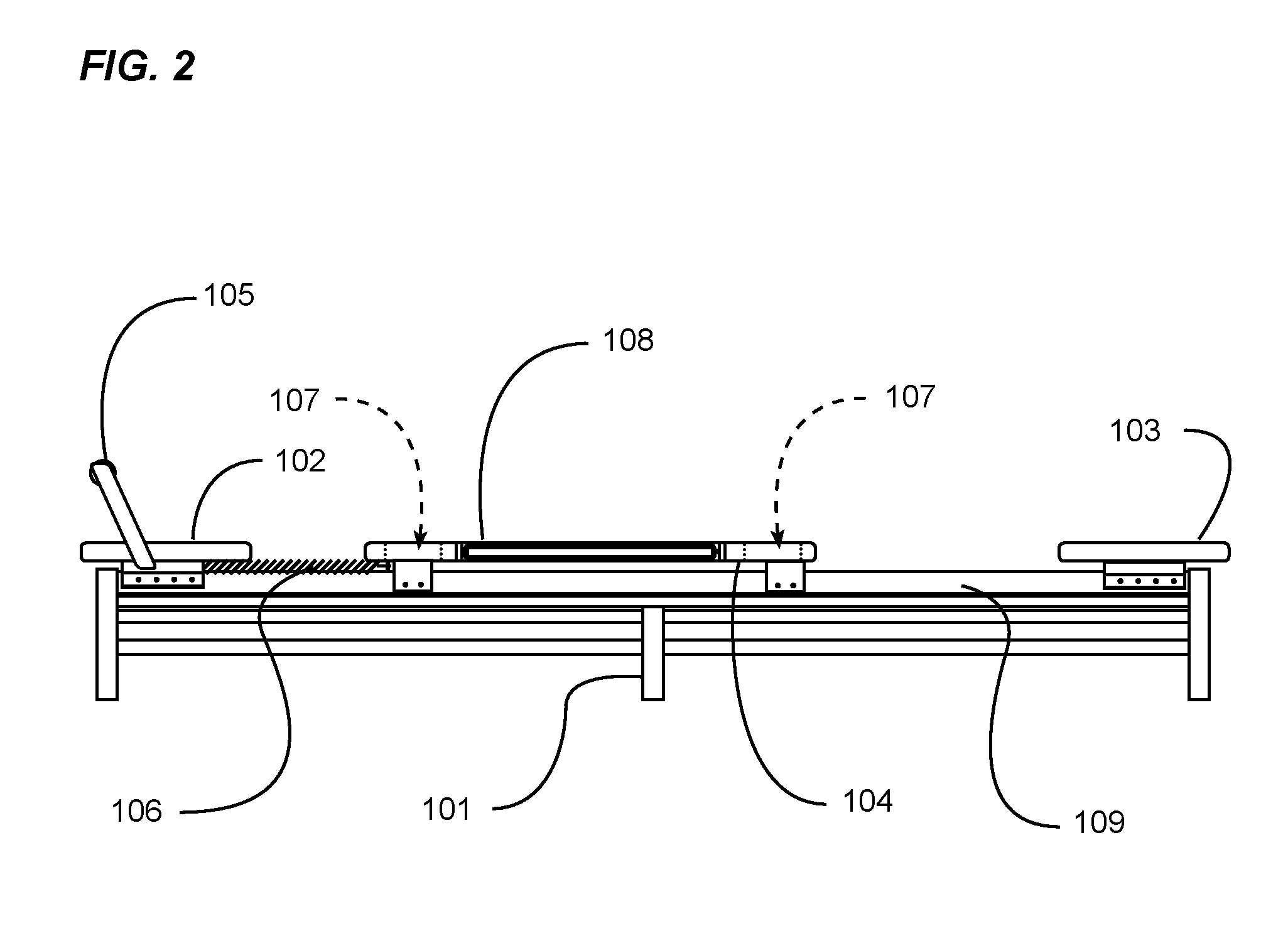
[0028]Turning now descriptively to the drawings, in which similar reference characters denote similar elements throughout the several views, FIGS. 1 through 8B illustrate an exercise machine carriage handle system, which comprises a frame having a track, a carriage movably connected to the track, a bias member connected between the frame and the carriage, a first handle connected to the carriage near the first side, and a second handle connected to the carriage near the second side. The first handle and second handle are adapted for grasping with a first hand and a second hand respectively of a user during the performance of an exercise on the exercise machine.

[0029]FIG. 1 is an exemplary diagram showing an isometric view of an improved Pilates apparatus.

[0030]In the drawing, a Pilates apparatus 100 is shown comprising a support structure with a plurality of support feet 101, a pair of parallel rails 109 extending longitudinally substantially the length of the apparatus ...


PUM


Abstract

An exercise machine carriage handle system for providing handles for an exerciser to grasp with their hands thereby expanding the type of exercises that may be performed. The exercise machine carriage handle system generally includes a frame having a track, a carriage movably connected to the track, a bias member connected between the frame and the carriage, a first handle connected to the carriage near the first side, and a second handle connected to the carriage near the second side. The first handle and second handle are adapted for grasping with a first hand and a second hand respectively of a user during the performance of an exercise on the exercise machine.

Description

CROSS REFERENCE TO RELATED APPLICATIONS[0001]The present application is a continuation-in-part of U.S. application Ser. No. 14 / 065,851 filed on Oct. 29, 2013 (Docket No. LAGR-005), wherein U.S. application Ser. No. 14 / 065,851 is a continuation-in-part of U.S. application Ser. No. 13 / 924,088 filed on Jun. 21, 2013 now issued as U.S. Pat. No. 9,119,989 (Docket No. LAGR-003), wherein U.S. application Ser. No. 14 / 065,851 claims priority to U.S. Provisional Application No. 61 / 719,763 filed Oct. 29, 2012 (Docket No. LAGR-002), and wherein U.S. application Ser. No. 14 / 065,851 claims priority to U.S. Provisional Application No. 61 / 806,655 filed Mar. 29, 2013 (Docket No. LAGR-006). Each of the aforementioned patent applications, and any applications related thereto, is herein incorporated by reference in their entirety.[0002]The present application is also a continuation-in-part of U.S. application Ser. No. 14 / 066,402 filed Oct. 29, 2013 (Docket No. LAGR-012), which claims the benefit of U.S...

Claims


Application Information

Patent Timeline
IPC IPC(8): A63B21/04A63B21/00
CPCA63B21/4035A63B21/0428A63B21/00065A63B21/023A63B21/055A63B21/4034A63B22/0007A63B22/001A63B22/0046A63B22/0089A63B22/203A63B2023/003A63B2208/0219A63B2208/0223A63B2225/09A63B21/4045A63B23/03508A63B23/03516A63B23/03575A63B23/04A63B23/12A63B71/0622A63B2071/0633A63B2071/0694
Inventor LAGREE, SEBASTIEN ANTHONY LOUISHAMILTON, JOHN C.
Owner LAGREE TECH INC
Why Eureka
Try Eureka