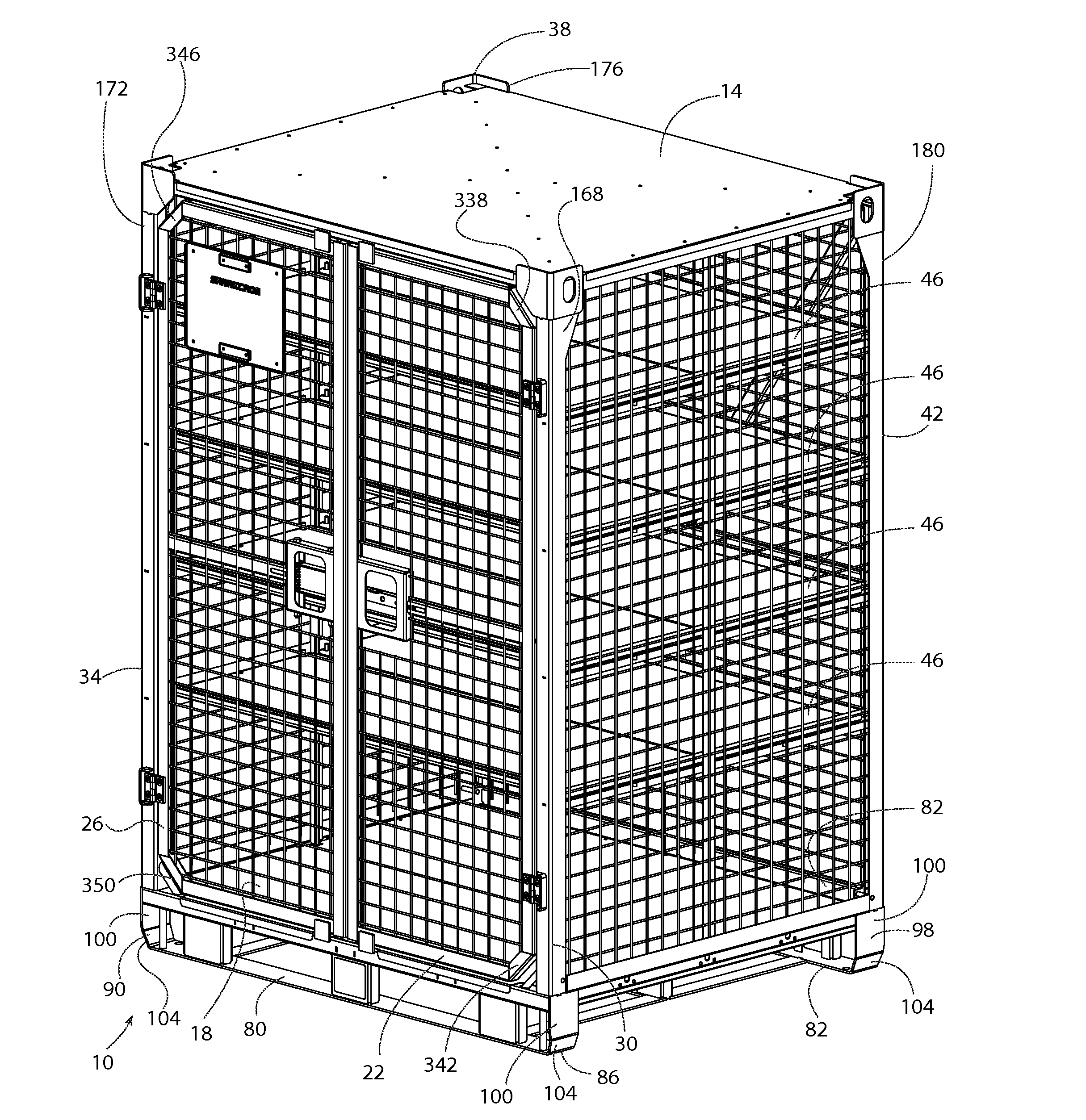
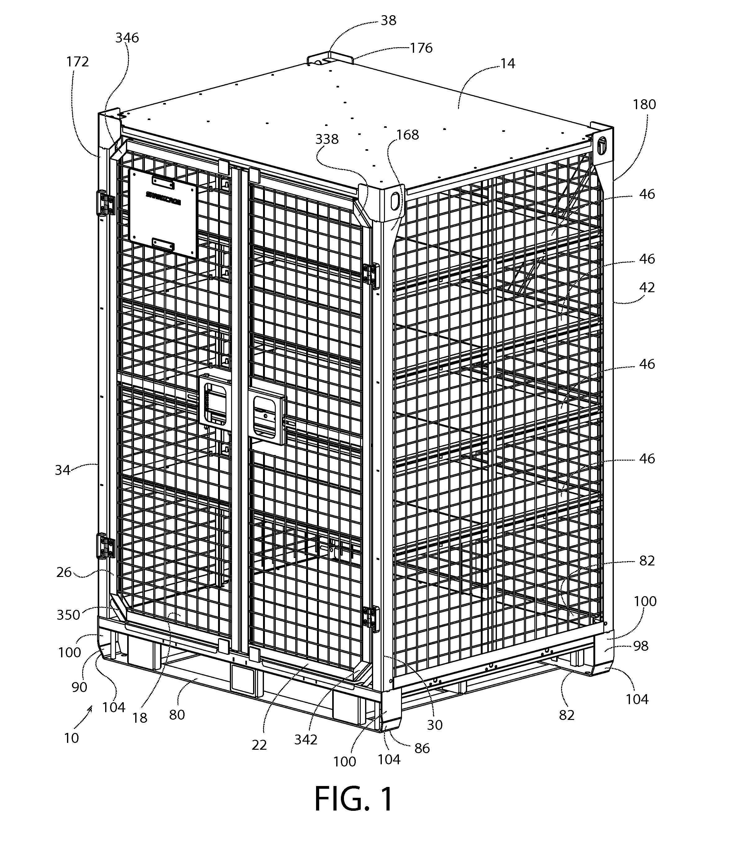
A cargo transportation locker, the locker comprising: a floor; a first corner post in communication with the floor; a second corner post in communication with the floor; a third corner post in communication with the floor; a fourth corner post in communication with the floor; a first door in rotatable communication with the first corner post, the first door comprising: a first angled door member located in an upper corner of the first door adjacent the first post, where the first angled door member makes an angle with the top side of the first door of less than 90°, and makes an angle of less than 90° with the hinged side of the first door; a second angled door member located in a lower corner of the first door adjacent the first post, where the first angled door member makes an angle with the bottom side of the first door of less than 90°, and makes an angle of less than 90° with the hinged side of the first door; a second door in rotatable communication with the second corner post; the second door comprising: a third angled door member located in an upper corner of the second door adjacent the second post, where the third angled door member makes an angle with the top side of the second door of less than 90°, and makes an angle of less than 90° with the hinged side of the second door; a fourth angled door member located in a lower corner of the second door adjacent the second post, where the fourth angled door member makes an angle with the bottom side of the second door of less than 90°, and makes an angle of less than 90° with the hinged side of the second door. A cargo transportation locker, the locker comprising: a floor; a first corner post in communication with the floor; a second corner post in communication with the floor; a third corner post in communication with the floor; a fourth corner post in communication with the floor; a first door in rotatable communication with the first corner post, the first door comprising: a first angled door member located in an upper corner of the first door adjacent the first post, where the first angled door member makes an angle with the top side of the first door of less than 90°, and makes an angle of less than 90° with the hinged side of the first door; a second angled door member located in a lower corner of the first door adjacent the first post, where the first angled door member makes an angle with the bottom side of the first door of less than 90°, and makes an angle of less than 90° with the hinged side of the first door; a first
door handle; the first
door handle comprising: a slideable member configured to slide from the first door to the second door, and when slid into the second door, the first and second
doors are locked in a closed orientation; a first slideable member hole, located in the slideable member, and when first slideable member hole is padlocked, the first and second
doors are locked in a closed orientation; a second slideable member hole, located in the slideable member, and when second slideable member hole is padlocked, the slideable member does not
restrict the second door from opening and closing. a second door in rotatable communication with the second corner post; the second door comprising: a third angled door member located in an upper corner of the second door adjacent the second post, where the third angled door member makes an angle with the top side of the second door of less than 90°, and makes an angle of less than 90° with the hinged side of the second door; a fourth angled door member located in a lower corner of the second door adjacent the second post, where the fourth angled door member makes an angle with the bottom side of the second door of less than 90°, and makes an angle of less than 90° with the hinged side of the second door; a second
door handle, the second door
handle comprising: an upper spring loaded sliding member; at least one spring in communication with the supper spring loaded sliding member; a lower spring loaded sliding member in communication with the at least one spring; an upper locking rod in communication with the upper spring loaded member; a lower locking rod in communication with the lower spring loaded member; a first top support member in communication with the first corner post and the second corner post, the first top support member having a upper rod hole in its underside; a first floor support member located beneath the floor and in communication with the first corner post and second corner post, the first floor support member having a lower rod hole in its upper side; and where when the upper spring loaded sliding member and lower spring loaded sliding member are fully spread apart, the upper locking rod extends through the upper rod hole, and the lower locking rod extends through the lower rod hole thereby locking the second door to the locker, and when the upper spring loaded sliding member and lower spring loaded sliding member are squeezed together, the upper locking rod retracts from the upper rod hole and the lower locking rod retracts from the lower rod hole, thereby unlocking the second door from the locker.

