
Autoinjector

a technology of auto-injector and injection needle, which is applied in the direction of automatic syringes, intravenous devices, injection needles, etc., can solve the problems of inability to the injection may stop and may not deliver the intended dose, and the force required to push the button/plunger may be too high

Active Publication Date: 2016-05-26
SANOFI AVENTIS DEUT GMBH
View PDF4 Cites 17 Cited by
  • Summary
  • Abstract
  • Description
  • Claims
  • Application Information

AI Technical Summary

Benefits of technology

The present invention provides an improved autoinjector with a needle shroud and plunger mechanism. The needle shroud is movable between a first extended position and a retracted position, and the plunger is rotatable between a first rotational position and a second rotational position. The needle shroud is operably coupled to the plunger and the plunger is biased to move the needle shroud in a distal direction relative to the case. The autoinjector also includes a cap that engages a protective needle sheath and a shroud spring biasing the needle shroud in a distal direction relative to the case. The plunger includes plunger bosses that engage with the case and a plunger rib that engages the needle shroud to rotate the plunger. The invention provides improved safety and ease of use for the autoinjector.

Problems solved by technology

Administering an injection is a process which presents a number of risks and challenges for users and healthcare professionals, both mental and physical.
There are numerous disadvantages associated with this approach.
For example, if the button / plunger is released prematurely, the injection will stop and may not deliver an intended dose.
Further, the force required to push the button / plunger may be too high (e.g., if the user is elderly or a child).

Method used


Image

  • Autoinjector
  • Autoinjector
  • Autoinjector

Examples


Embodiment Construction

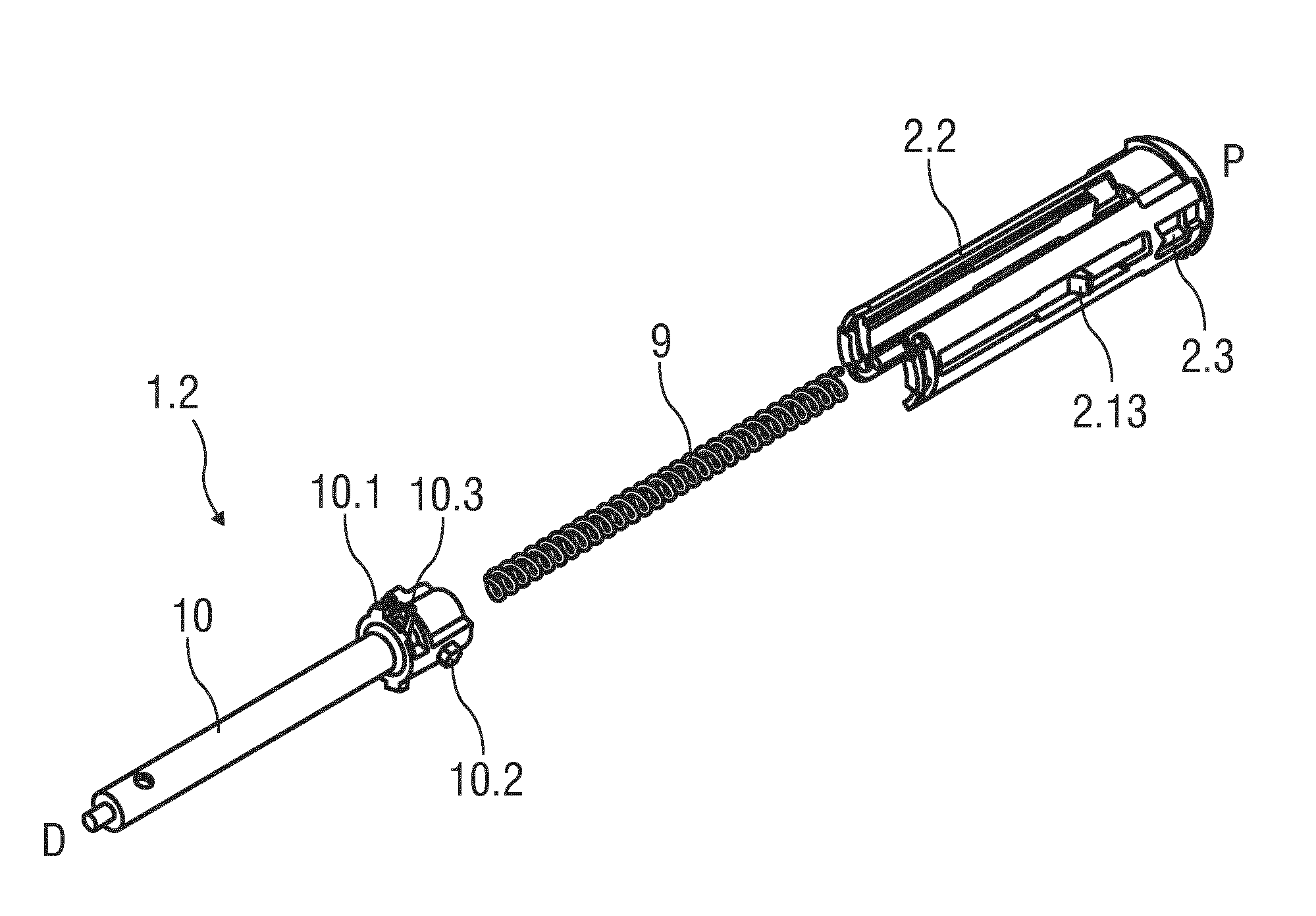
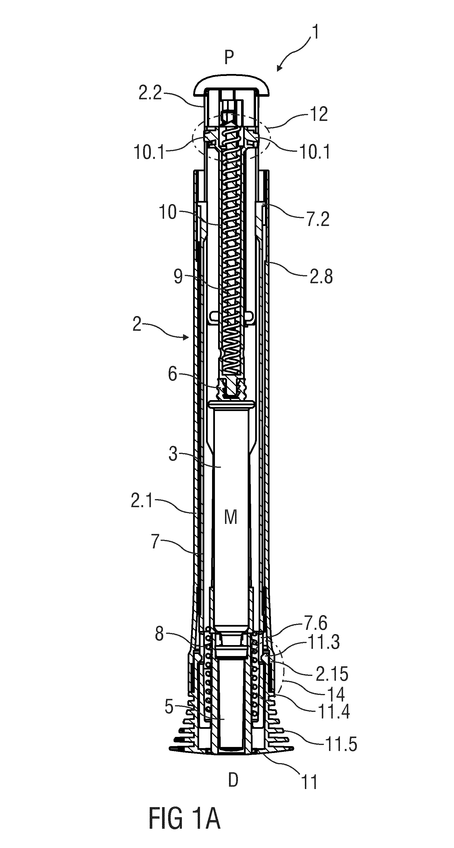
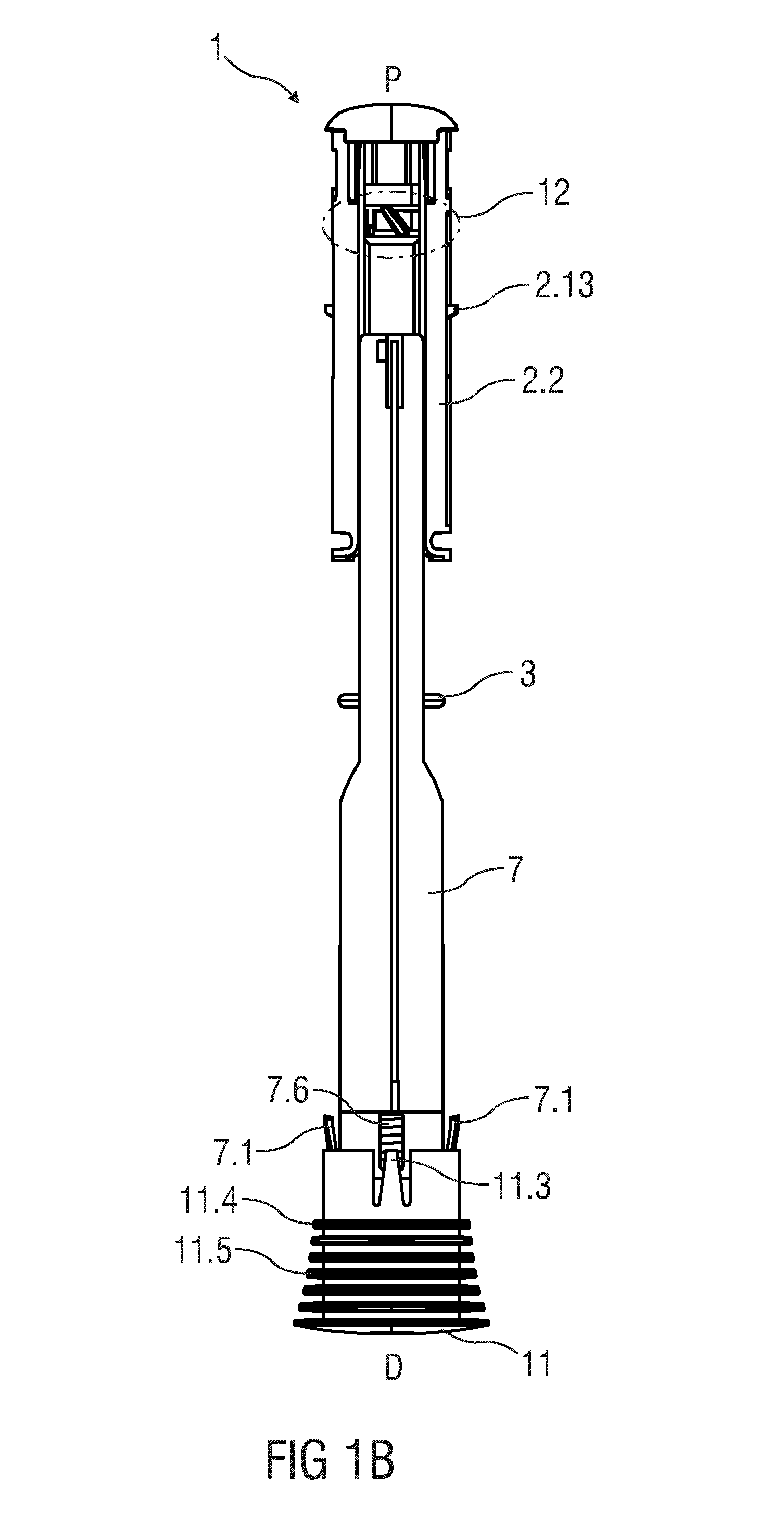
[0046]FIG. 1A is a longitudinal section of an exemplary embodiment of an autoinjector 1 according to the present invention during assembly. The autoinjector 1 comprises a case 2 comprising a front case 2.1 and a rear case 2.2. The case 2 is adapted to hold a medicament container, such as a syringe 3. The syringe 3 may be a pre-filled syringe and have a needle 4 arranged at a distal end. When the autoinjector 1 and / or the syringe 3 are assembled, a protective needle sheath 5 may be removably coupled to the needle 4. The protective needle sheath 5 may be a rubber needle sheath or a rigid needle sheath (which is composed of rubber and a full or partial plastic shell). A stopper 6 is arranged for sealing the syringe 3 proximally and for displacing a medicament M contained in the syringe 3 through the needle 4. In other exemplary embodiments, the medicament container may be a cartridge which includes the medicament M and engages a removable needle (e.g., by threads, snaps, friction, etc....


PUM


Abstract

Describe is an autoinjector (1) comprising a case (2) adapted to hold a medicament container having a needle (4), a needle shroud (7) telescopically coupled to the case (2) and movable between a first extended position (FEP) relative to the case (2) in which the needle (4) is covered and a retracted position (RP) relative to the case (2) in which the needle (4) is exposed, and a plunger (10) rotationally and slidably disposed in the case (2). The plunger (10) is rotatable relative to the case (2) between a first rotational position in which the plunger (10) is engaged to the case (2) and a second rotational position in which the plunger (10) disengages the case (2). The needle shroud (7) is operably coupled to the plunger (10). When the needle shroud (7) translates from the first extended position (FEP) to the retracted position (RP), the plunger (10) rotates from the first rotational position to the second rotational position.

Description

TECHNICAL FIELD[0001]The invention relates to an autoinjector.BACKGROUND OF THE INVENTION[0002]Administering an injection is a process which presents a number of risks and challenges for users and healthcare professionals, both mental and physical. Injection devices typically fall into two categories—manual devices and autoinjectors. In a conventional manual device, manual force is required to drive a medicament through a needle. This is typically done by some form of button / plunger that has to be continuously pressed during the injection. There are numerous disadvantages associated with this approach. For example, if the button / plunger is released prematurely, the injection will stop and may not deliver an intended dose. Further, the force required to push the button / plunger may be too high (e.g., if the user is elderly or a child). And, aligning the injection device, administering the injection and keeping the injection device still during the injection may require dexterity which...

Claims


Application Information

Patent Timeline
Patent Type & Authority Applications(United States)
IPC IPC(8): A61M5/315A61M5/32
CPCA61M5/3202A61M5/31585A61M5/2033A61M2005/206A61M2005/3247A61M2005/3267
Inventor MOSEBACH, CARSTENKEMP, THOMAS
Owner SANOFI AVENTIS DEUT GMBH
Learn More