Mechanical costume wings

a technology of mechanical wings and wings, applied in the field of mechanical wings, can solve the problems of lack of animated or movable wings of costumes or costume accessories, or “life-like” wings

Inactive Publication Date: 2016-08-04
DIETRICK LAUREEN BECK
View PDF6 Cites 6 Cited by
  • Summary
  • Abstract
  • Description
  • Claims
  • Application Information

AI Technical Summary

Benefits of technology

[0008]Each wing connects to the harness with a hinge near the wearer's shoulder blade. The hinge allows each wing to swing approximately 90 degrees from directly behind the wearer to the wearer's sides. Each wing also has a joint allowing the wing to move from a lowered or contracted position to

Problems solved by technology

However, most such costumes have static wings that are simply attached the wearer's back, or, at most, move only upon movement

Method used


Image

  • Mechanical costume wings
  • Mechanical costume wings
  • Mechanical costume wings

Examples


Embodiment Construction

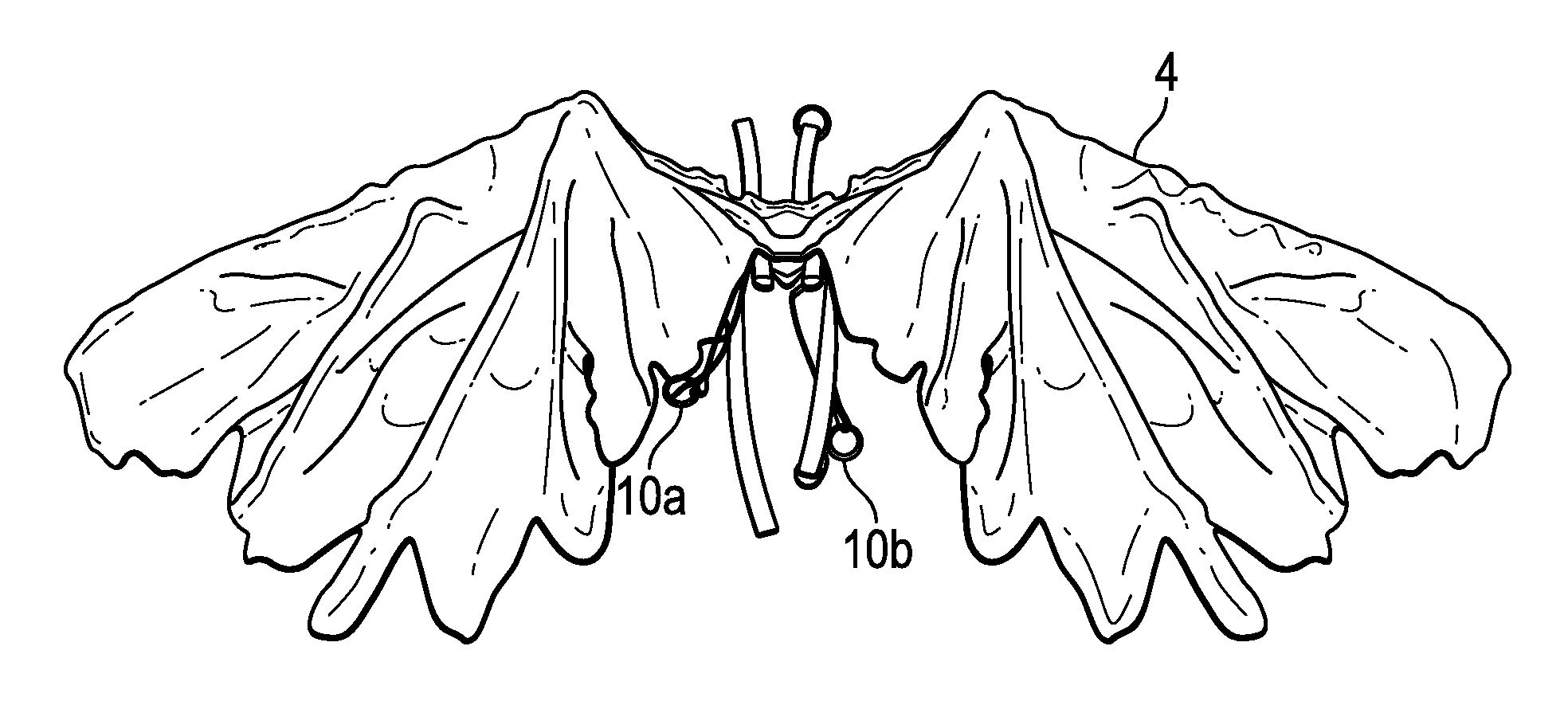
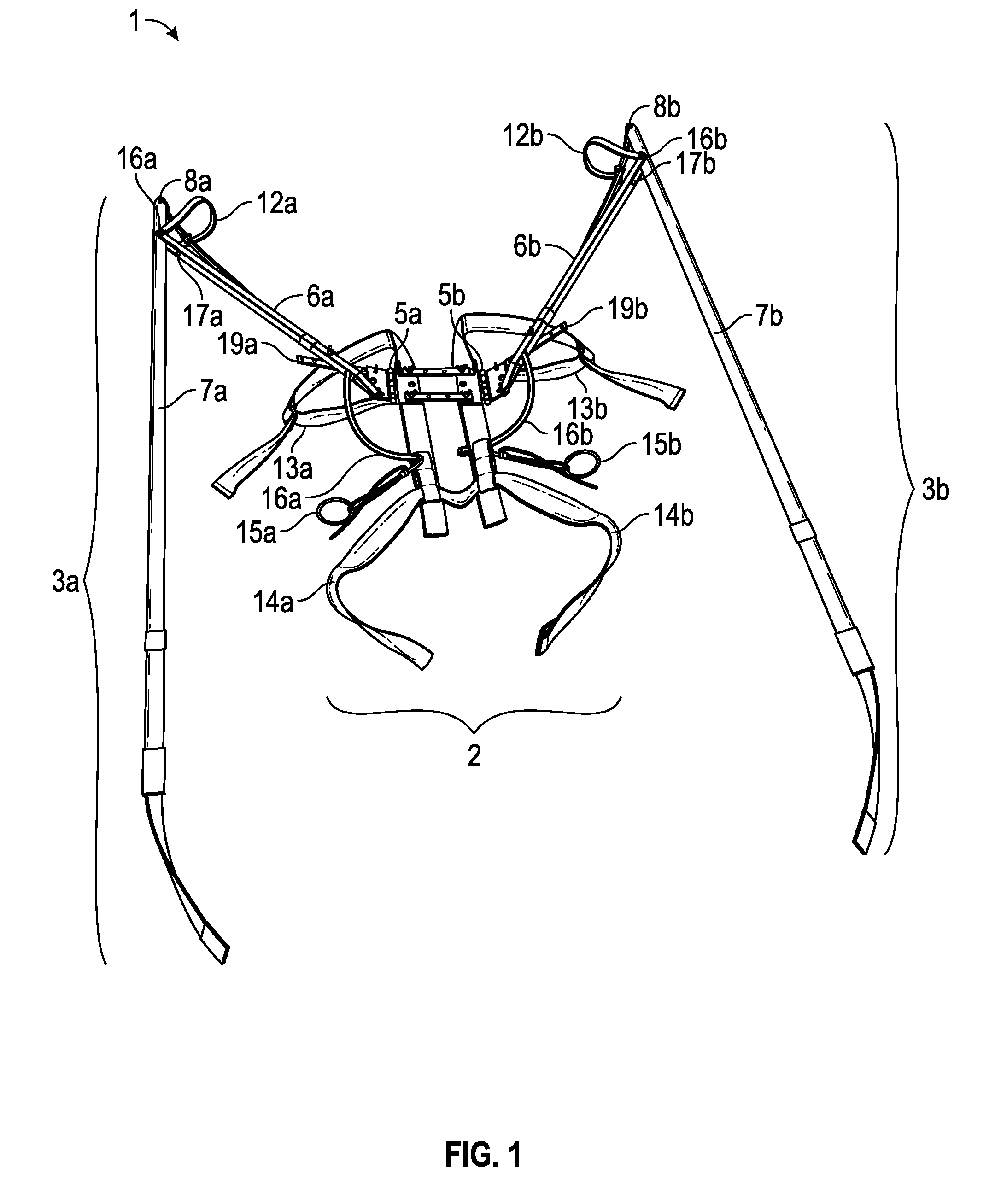
[0017]Referring now to the figures, various embodiments of the costume wing 1 of this invention is shown. The invention includes a mechanism comprising a harness 2 with two symmetrical wing structures 3a, 3b configured to be worn on the wearer's 11 back 11b. The invention further comprises an outer aesthetic covering 4 that can be fanciful in design, or that can mimic the actual appearance of a creature's wings. The outer cover is removable and replaceable with alternative outer coverings. The invention further comprises a method of displaying a fanciful wing structure and design on a wearer 11.

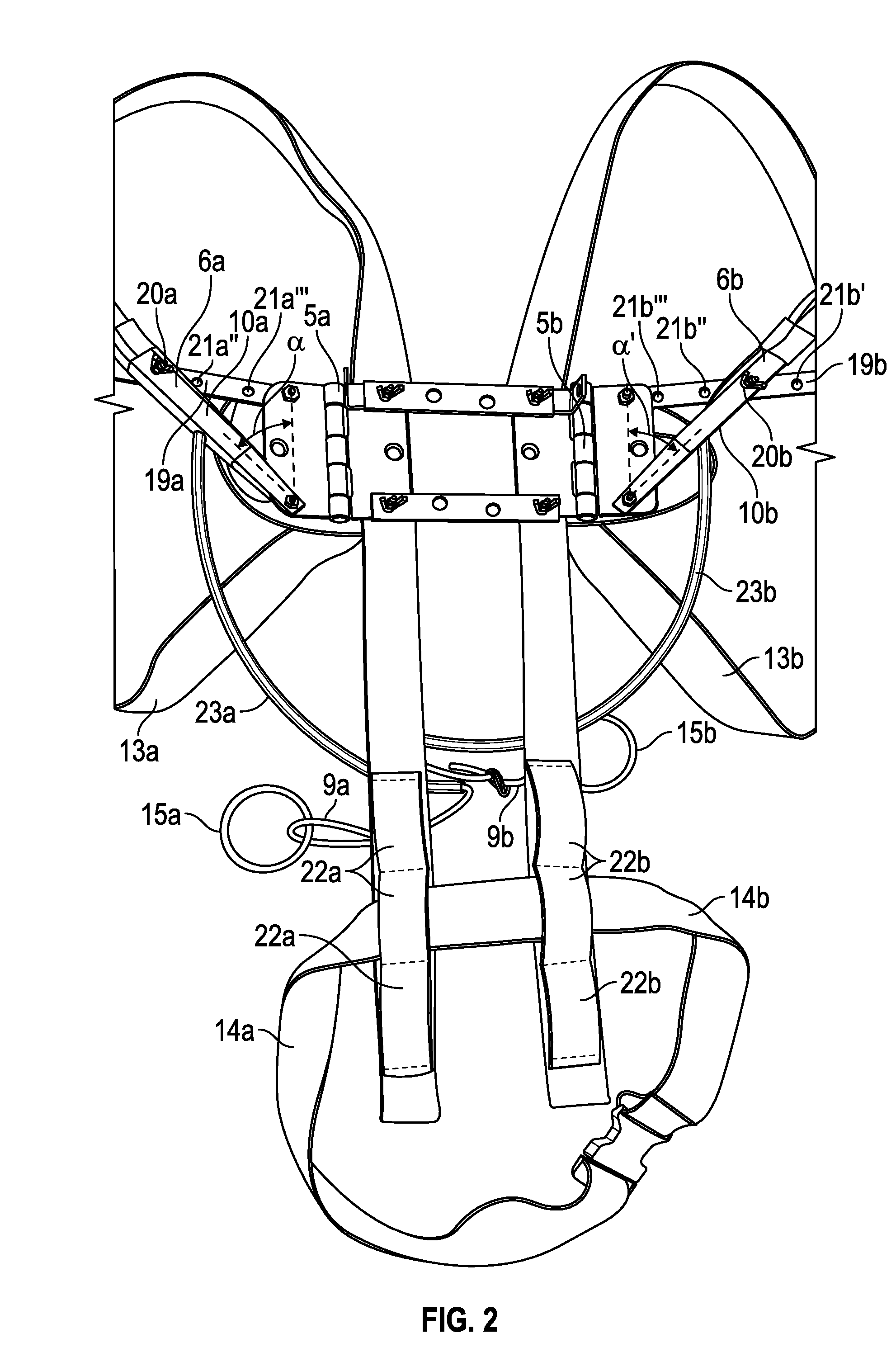
[0018]The mechanism mimics the appearance of articulated wings. Each wing 3a, 3b connects to the harness 2 with a hinge 5a, 5b near the wearer's 11 shoulder blade, and is referred to herein as the wing shoulder and the harness shoulder. The hinge 5a, 5b allows each wing 3a, 3b to swing independently and approximately 90 degrees from directly behind the wearer 11 to the sides of the wearer 11....


PUM


Abstract

A costume wing, and a kit for producing a costume wing, having an internal structure mechanically capable of movement to simulate the flapping or spreading of wings, and an interchangeable external decorative cover.

Description

BACKGROUND OF THE INVENTION[0001]1. Technical Field[0002]This invention relates generally to the fields of costumes, costume accessories, costume wings, and mechanical costume wings capable of wearer animation. This invention also relates to the fields of mechanical costume wings having an internal support and movement structure and an external decorative covering that can be removed and replaced with alternative external decorative coverings.[0003]2. Prior Art[0004]People have long dressed up in costumes. Many costumes are simply clothing to invoke a different look, such as prehistoric or medieval eras. Other costumes simulate animals or mythological creatures. Still other costumes have lights, bells, and whistles for a multi-media effect. This is a long way of saying that there is no limit to the type of costumes available.[0005]Many people like animated costumes. For example, birds or butterflies have wings, and costumes simulating birds or butterflies preferably also have wings....

Claims


Application Information

Patent Timeline
IPC IPC(8): A63J7/00
CPCA63J7/005
Inventor DIETRICK, LAUREEN BECK
Owner DIETRICK LAUREEN BECK
Why Eureka
Try Eureka