
Pressure fluctuation buffering mechanism and applicator

a buffering mechanism and pressure fluctuation technology, applied in the direction of writing connectors, printing, writing implements, etc., can solve the problems of pressure fluctuation, ink leakage from the nib, ink difficulty in being discharged from the nib, etc., to achieve buffering the effect of pressure fluctuation, reducing the probability of paint leakage, and maintaining the practicality

Active Publication Date: 2016-09-01
V SPARK +1
View PDF2 Cites 1 Cited by
  • Summary
  • Abstract
  • Description
  • Claims
  • Application Information

AI Technical Summary

Benefits of technology

The present invention is a pressure fluctuation buffering mechanism that can be used in writing instruments and applicators. The mechanism is designed to prevent paint leakage and ensure proper ink flow performance. Its high ability to buffer pressure fluctuation makes it a practical solution for maintaining the functionality of writing instruments.

Problems solved by technology

Various problems occur when pressure fluctuation is generated in the ink tank due to variations in the environmental conditions (such as pressure or ambient temperature) under which such an applicator is used.
For example, if pressure in the ink tank is increased, the ink leaks from a nib.
If pressure in the ink tank is decreased, on the other hand, the ink has difficulty in being discharged from the nib.

Method used


Image

  • Pressure fluctuation buffering mechanism and applicator
  • Pressure fluctuation buffering mechanism and applicator
  • Pressure fluctuation buffering mechanism and applicator

Examples


Embodiment Construction

[0052]An embodiment of the present invention will be described below with reference to the accompanying drawings.

(Applicator)

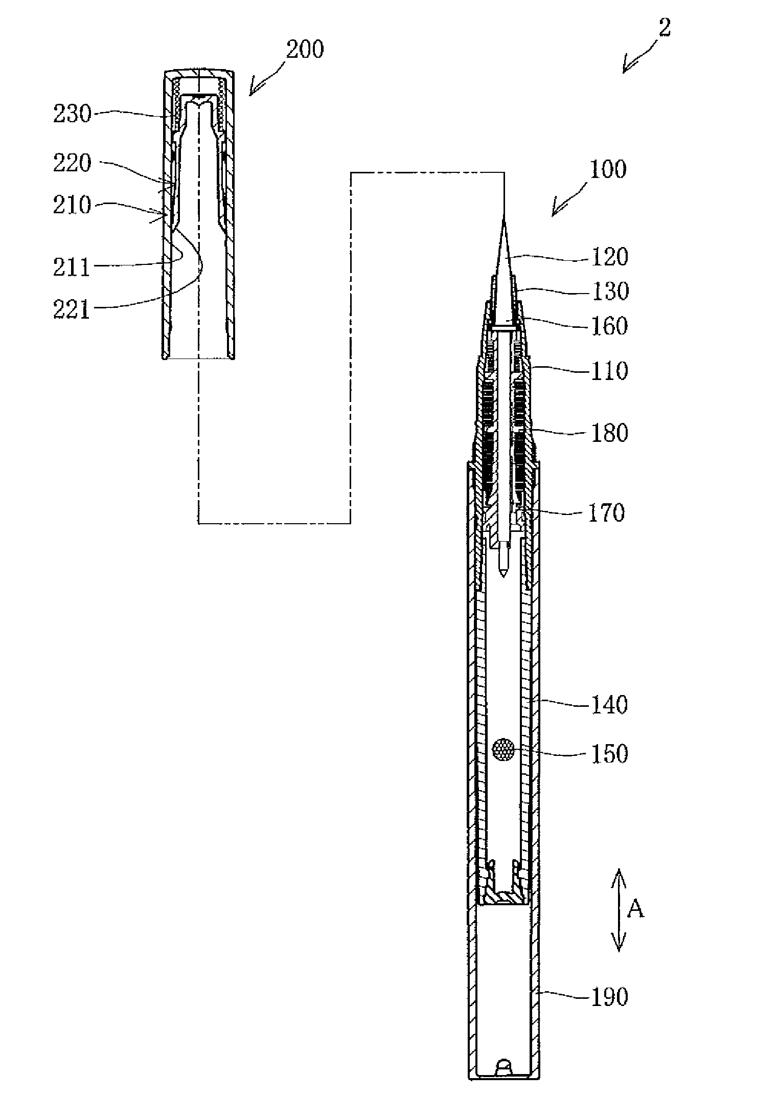
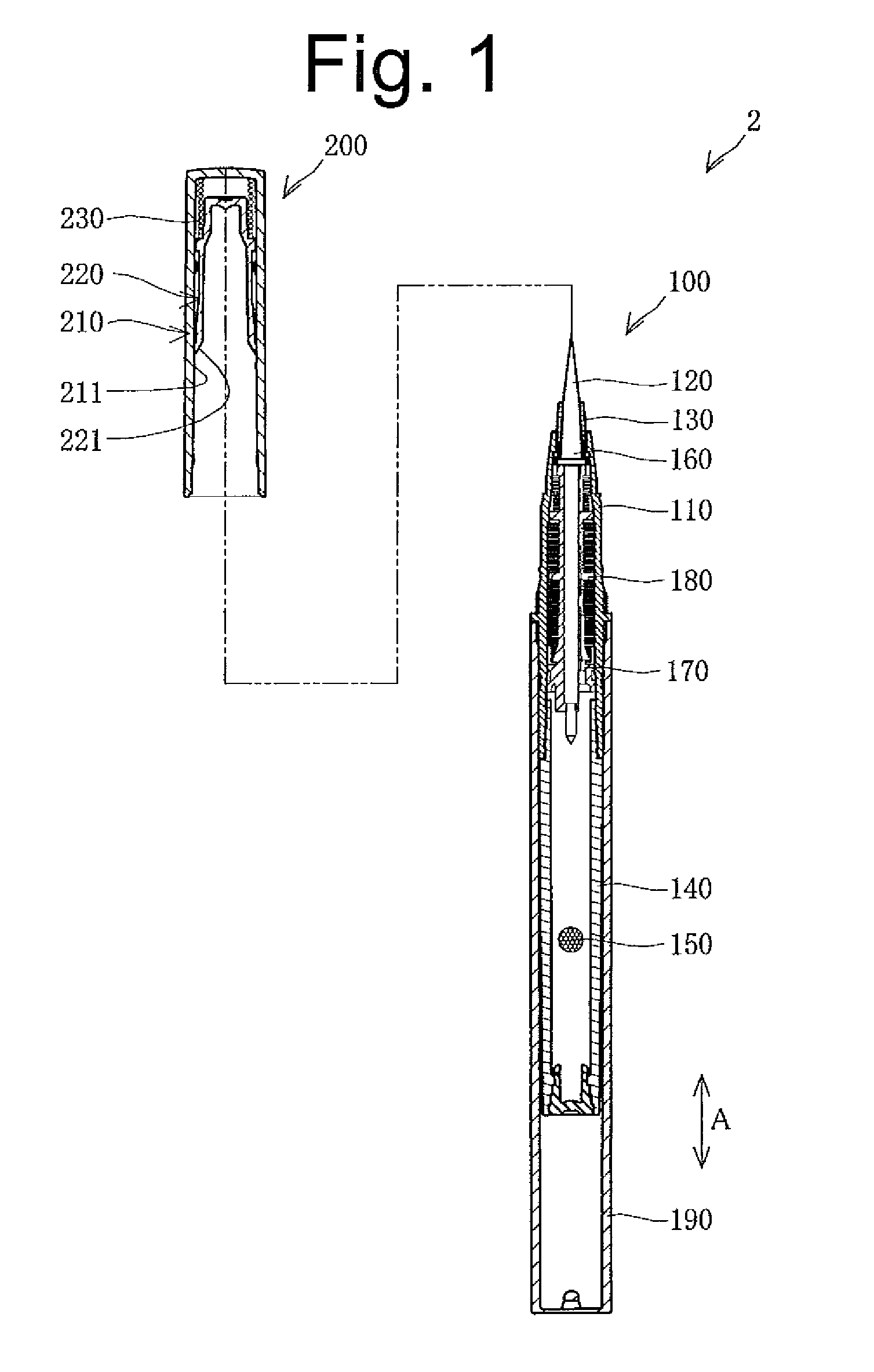
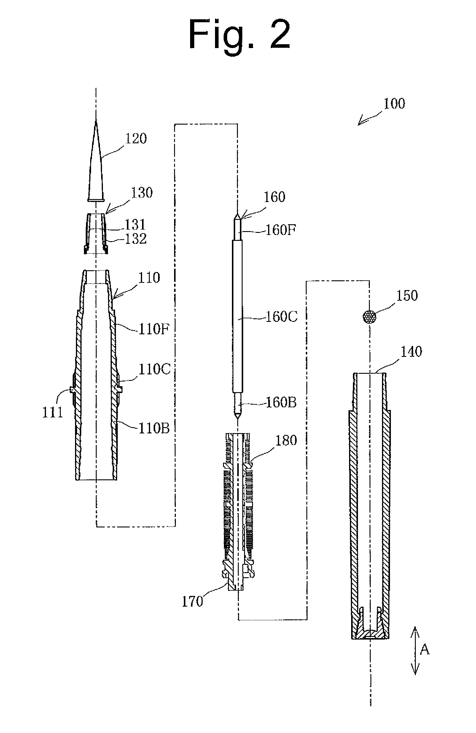
[0053]As shown in FIG. 1, an applicator 2 includes a rod-like applicator body 100 extending long in a front-rear direction, and a cap 200 detachably provided in a front end portion of the applicator body 100.

(Cap)

[0054]The cap 200 includes: an outer cap 210; an inner cap 220 disposed inside the outer cap 210; and an inner cap spring 230 disposed inside the outer cap 210 for biasing the inner cap 220. The outer cap 210 and the inner cap 220 are each made of a synthetic resin such as polypropylene (PP).

[0055]An engagement projection 211 is provided on the inner peripheral surface of the outer cap 210. The engagement projection 211 engages with a tip 221 of the inner cap 220. In the internal space of the outer cap 210, the inner cap 220 is movable between an engaged position at which the tip 211 engages with the engagement projection 211 and an unengaged position...


PUM


Abstract

A pressure fluctuation buffering mechanism includes a buffer space connected to a brush via a paint flow space (a paint tank and a paint feeder) through which paint flows. The pressure fluctuation buffering mechanism buffers pressure fluctuation in the paint tank by the flow of paint and air between the paint flow space and the buffer space. The pressure fluctuation buffering mechanism includes a first buffer space forming member for forming a first buffer space in the buffer space, and a second buffer space forming member for forming a second buffer space in the buffer space. The paint between the first buffer space and the paint flow space flows more easily than the paint between the second buffer space and the paint flow space.

Description

TECHNICAL FIELD[0001]The present invention relates to a pressure fluctuation buffering mechanism and an applicator.BACKGROUND ART[0002]Applicators (for example, fountain pens) each including an ink tank for accommodating ink have been known in the art. Various problems occur when pressure fluctuation is generated in the ink tank due to variations in the environmental conditions (such as pressure or ambient temperature) under which such an applicator is used. For example, if pressure in the ink tank is increased, the ink leaks from a nib. If pressure in the ink tank is decreased, on the other hand, the ink has difficulty in being discharged from the nib.[0003]To solve such a problem, a writing instrument having a pressure fluctuation buffering mechanism including: a comb groove for retaining ink; an ink flow groove provided perpendicular to the comb groove; and an air flow groove provided perpendicular to the comb groove to solve the problem caused by pressure fluctuation in an ink t...

Claims


Application Information

Patent Timeline
Patent Type & Authority Applications(United States)
IPC IPC(8): B43K8/04B43K23/12B43K8/08B43K8/02B43K8/03
CPCB43K8/04B43K8/02B43K23/128B43K8/08B43K8/03B43K7/105
Inventor KAWASAKI, MASAYUKI
Owner V SPARK
Learn More