Liquid container
a liquid container and container body technology, applied in printing and other directions, can solve the problems of design problems, inability to supply ink, increase the cost of components, etc., and achieve the effect of simple and reliable mounting
- Summary
- Abstract
- Description
- Claims
- Application Information
AI Technical Summary
Benefits of technology
Problems solved by technology
Method used
Image
Examples
second embodiment
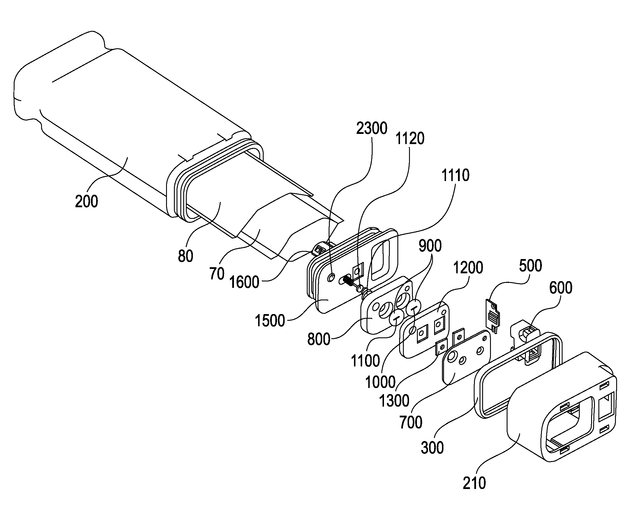
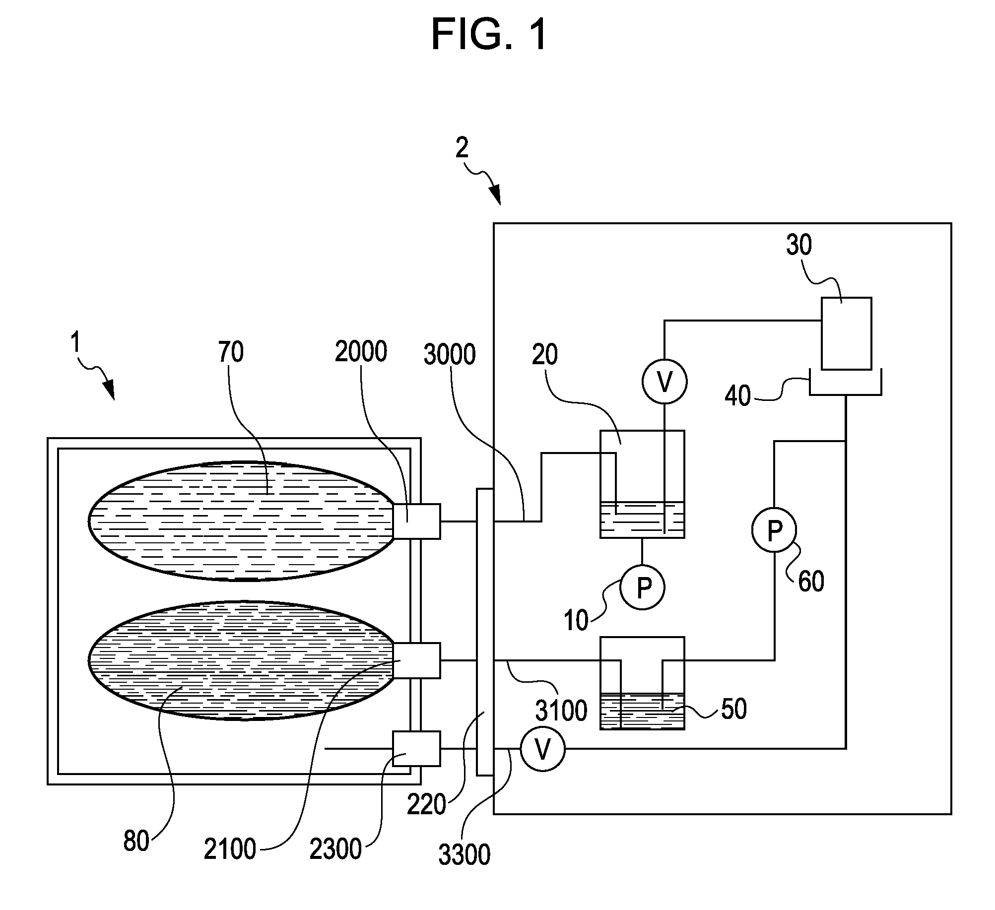
[0053]FIG. 8 shows a second embodiment incorporating the present invention. In this embodiment, the interior of the ink cartridge 1 is divided into two chambers. A chamber to which the ink-supply joint member 2000 connects has the ink bag 70, and a chamber to which the waste-ink-recovery joint member 2100 connects has the waste-ink bag 80.
[0054]The chamber that accommodates the waste-ink bag 80 is configured to be sealed when the ink cartridge 1 is mounted to the ink-jet printer 2. By reducing the pressure around the waste-ink bag 80, the waste-ink bag 80 can be expanded to recover the waste ink. Since the interior of the ink cartridge 1 is divided into two, the surroundings of the ink bag 70 can be communicated with the air. This allows independent ink supply without reducing the pressure around the ink bag 70. The chamber that accommodates the ink bag 70 can also be configured to be sealed when the ink cartridge 1 is mounted to the ink-jet printer 2. This also allows a liquid supp...
first embodiment
[0055]Also in this embodiment, the fitted portion 2210 and the pressure-reducing connecting portion 2300 for positioning can be provided coaxially. The order of detachment from the ink-jet printer 2 may be configured such that the pressure-reducing connecting portion 2300 can be first detached from the ink-jet printer 2. This offers the same advantages as the
[0056]By coaxially disposing the fitted portion 2210 and the pressure-applying connecting portion (not shown) and by satisfying the detaching sequence, the same advantages as those of the connecting portion of the pressure-reducing mechanism can be provided.
third embodiment
[0057]FIG. 9 shows a For the connection structure of the ink cartridge 1, as shown in FIG. 9, the fitted portions 2200 and 2210, the ink-supply joint member 2000, and the waste-ink-recovery joint member 2100 may be arranged on a straight line. In this case, the fitted portion 2200 in which the pressure-reducing connecting portion 2300 is coaxially provided may be disposed higher in the direction of gravity than the ink-supply joint member 2000 and the waste-ink-recovery joint member 2100 when the ink cartridge 1 is mounted to the ink-jet printer 2. This can prevent ink from flowing into the pump 60, as shown in FIG. 7, even if ink leaks from the ink-supply joint member 2000 and the waste-ink-recovery joint member 2100.
[0058]The above-described embodiments are described when applied to a liquid container to be used for an ink-jet printer, and the liquid accommodated in the liquid container as ink used in image formation. However, the liquid accommodated in the liquid container is no...
PUM
 Abstract
Description
Claims
Application Information
 - R&D
- Intellectual Property
- Life Sciences
- Materials
- Tech Scout
- Unparalleled Data Quality
- Higher Quality Content
- 60% Fewer Hallucinations
Browse by: Latest US Patents, China's latest patents, Technical Efficacy Thesaurus, Application Domain, Technology Topic, Popular Technical Reports.
© 2025 PatSnap. All rights reserved.Legal|Privacy policy|Modern Slavery Act Transparency Statement|Sitemap|About US| Contact US: help@patsnap.com


