Liquid supplying apparatus, liquid ejecting apparatus and pressure control method

Inactive Publication Date: 2012-02-02
FUJIFILM CORP +1
View PDF1 Cites 30 Cited by
  • Summary
  • Abstract
  • Description
  • Claims
  • Application Information

AI Technical Summary

Benefits of technology

[0013]According to the present invention, in a liquid supplying apparatus in which a pressure absorbing device for absorbing a pressure fluctuation in a first flow channel is provided in the first flow channel, a pressure increase in the first flow channel is measured when a first pressure applying device is operated under a standard operation condition in which pressure in the first flow channel varies relatively moderately in proportion to a liquid feed amount to the first flow channel in a state where a liquid supply object and the first flow channe

Problems solved by technology

With an ink supplying system which performs back-pressure control by feeding of ink in an inkjet recording apparatus, variances in a performance of a pump for pressurizing ink may potentially cause the ink supplying system to lose its ability to appropriately control pressure and control ink feeding.
In particular, when a tube pump is applied as the pump used for ink feeding, such a loss in ability may be caused not only by variances in initial performance attributable to variances in size of parts used in the tube pump, an assembly variance of the tube pump, and a variance in an elasticity of a tube used for the tube pump, but also by a change over time in the elasticity of the tube.
However, since the technique disclosed in Japanese Patent Application Publication No. 2000-229422 measures pressure in a continuous inkjet recording apparatus in a state where ink is being ejected from a head due to feeding of the ink by a pump and therefore measures a pressure value which includes variations in flow channel resistance due to nozzle clogging or the like, it is difficult to describe that an isolated perfo

Method used


Image

  • Liquid supplying apparatus, liquid ejecting apparatus and pressure control method
  • Liquid supplying apparatus, liquid ejecting apparatus and pressure control method
  • Liquid supplying apparatus, liquid ejecting apparatus and pressure control method

Examples


first embodiment

General Configuration of Ink Supplying Apparatus

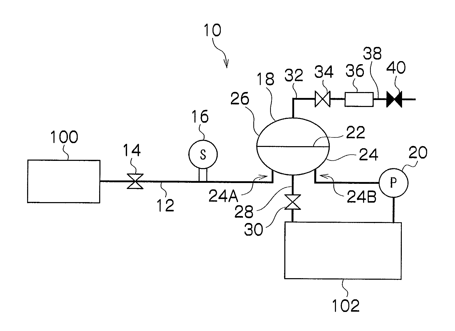
[0031]FIG. 1 is a block diagram showing a general configuration of an ink supplying apparatus according to a first embodiment of the present invention. An ink supplying apparatus 10 shown in FIG. 1 is a non-recycling ink supplying apparatus which supplies ink to an inkjet head (hereinafter, may also be simply referred to as a “head”) 100 from an ink tank 102 and which controls an internal pressure (back-pressure) of the head 100 by a feed amount of ink. As shown in FIG. 1, the ink supplying apparatus 10 includes a liquid flow channel 12 which communicates (is connected) with the head 100, a head valve 14 which switches between communication and noncommunication between the head 100 and the liquid flow channel 12, a pressure sensor 16 which measures an internal pressure of the liquid flow channel 12, a pressure absorbing chamber 18 which is provided in the liquid flow channel 12 and which performs pressure adjustment so as to suppress f...

second embodiment

[0076]Next, an ink supplying apparatus according to a second embodiment of the present invention will be described. FIG. 9 is a block diagram showing a schematic configuration of an ink supplying apparatus 200 according to the present embodiment. The following description will focus on components which differ from the ink supplying apparatus 10 described with reference to FIGS. 1 to 8.

General Configuration

[0077]The ink supplying apparatus 200 illustrated in FIG. 9 is a recycling ink supplying apparatus including a supply flow channel 202 and a recovery flow channel 212, wherein a supply flow channel pressure sensor 206 is provided in the supply flow channel 202 and a recovery flow channel pressure sensor 216 is provided in the recovery flow channel 212. In addition, a first pressure absorbing chamber 208 is provided with the supply flow channel 202 and a second pressure absorbing chamber 218 is provided with the recovery flow channel 212. The first pressure absorbing chamber 208 is ...


PUM


Abstract

A liquid supplying apparatus includes: a first flow channel configured to be switchable between a state of communication with a liquid supply object and a state of noncommunication with the liquid supply object; a first pressure applying device which applies pressure to liquid in the first flow channel; a first pressure absorbing device which absorbs a pressure fluctuation of the liquid in the first flow channel; a first measuring device which measures a pressure increase value in the first flow channel when the first pressure applying device is operated under a standard operating condition in which pressure in the first flow channel varies relatively moderately in proportion to a liquid feed amount to the first flow channel in the state of noncommunication where the liquid supply object and the first flow channel are not communicated with each other; a comparing device which compares the pressure increase value measured by the first measuring device with a predetermined pressure increase target value; and a pressure controlling device which controls the first pressure applying device according to a comparison result of the comparing device so as to correct the pressure applied into the first flow channel.

Description

BACKGROUND OF THE INVENTION[0001]1. Field of the Invention[0002]The present invention relates to a liquid supplying apparatus, a liquid ejecting apparatus, and a pressure control method, and in particular, relates to a pressure control technique related to liquid used for an inkjet head.[0003]2. Description of the Related Art[0004]With an ink supplying system which performs back-pressure control by feeding of ink in an inkjet recording apparatus, variances in a performance of a pump for pressurizing ink may potentially cause the ink supplying system to lose its ability to appropriately control pressure and control ink feeding. In particular, when a tube pump is applied as the pump used for ink feeding, such a loss in ability may be caused not only by variances in initial performance attributable to variances in size of parts used in the tube pump, an assembly variance of the tube pump, and a variance in an elasticity of a tube used for the tube pump, but also by a change over time i...

Claims


Application Information

Patent Timeline
IPC IPC(8): F15D1/00
CPCB41J2/175B41J29/38B41J11/002B41J2/17596Y10T137/8158Y10T137/0396B41J11/0024B41J11/0022
Inventor FURUKAWA, KOJIISOZAKI, JUNKATAOKA, MASAKI
Owner FUJIFILM CORP
Why Eureka
Try Eureka