Mobile communication system
a communication system and mobile technology, applied in the field of mobile communication system, can solve the problems of inability to fully estimate the transmission power of each radio base station, and the inability of the base station enb to fully estimate the transmission power of each radio base station, and achieve the effect of maximizing the transmission power of the mobile station
- Summary
- Abstract
- Description
- Claims
- Application Information
AI Technical Summary
Benefits of technology
Problems solved by technology
Method used
Image

Examples
first embodiment
of Present Invention
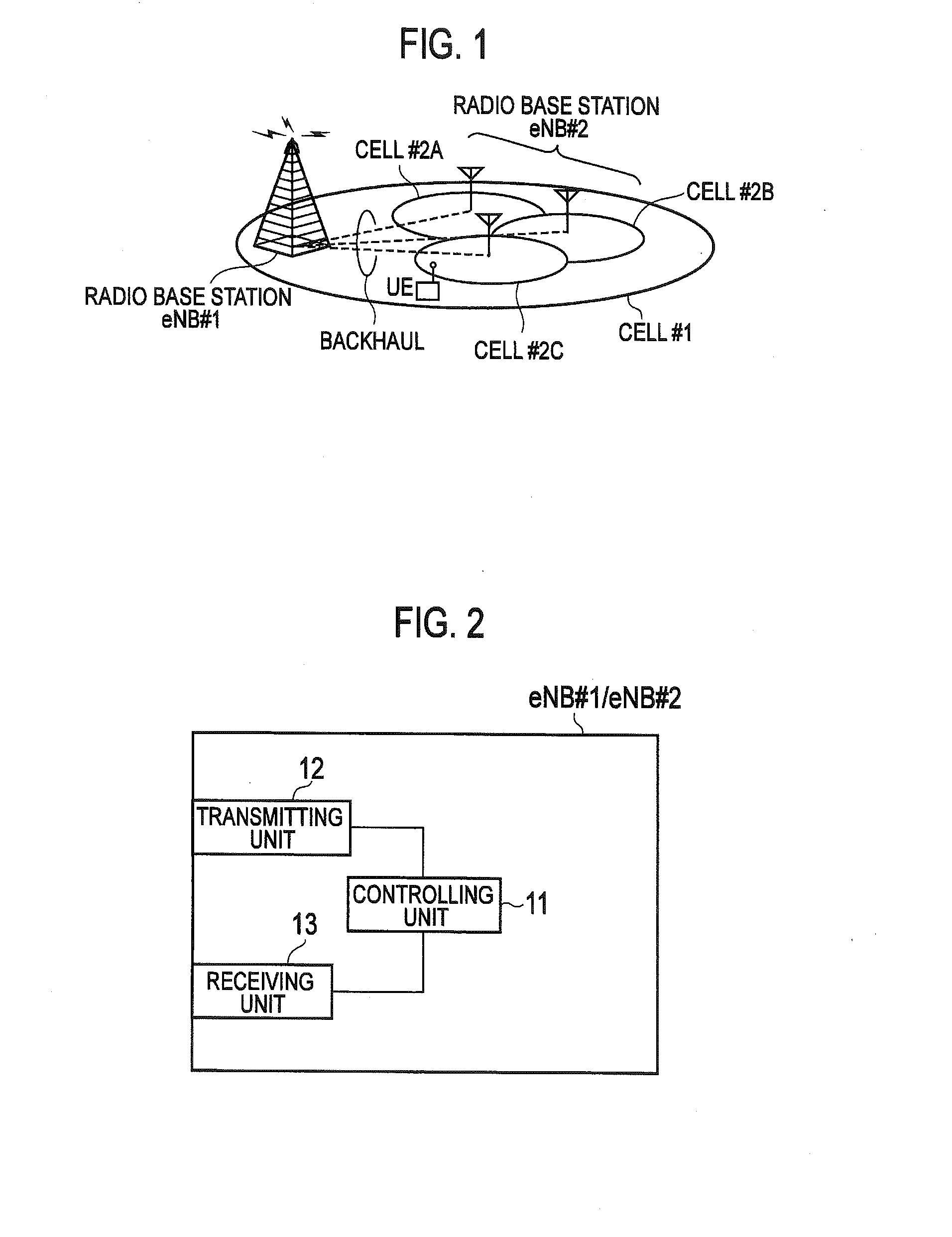
[0028]Referring now to FIGS. 1 and 2, a mobile communication system according to a first embodiment of the present invention will be explained below. The mobile communication system according to the present embodiment will be explained with an example of a mobile communication system of the LTE system. The present invention, however, can be applied to a mobile communication system other than that of the LTE system.
[0029]As shown in FIG. 1, the mobile communication system according to the present embodiment includes a radio base station eNB#1 that controls a cell #1, and a radio base station eNB#2 that controls cells #2A to #2C.
[0030]In the mobile communication system according to the present embodiment, the radio base station eNB#1 is a master radio base station (or, a macro radio base station) MeNB, and the radio base station eNB#2 is a slave radio base station (or, a small radio base station) SeNB.
[0031]Moreover, in the mobile communication system according to ...
second embodiment
of Present Invention
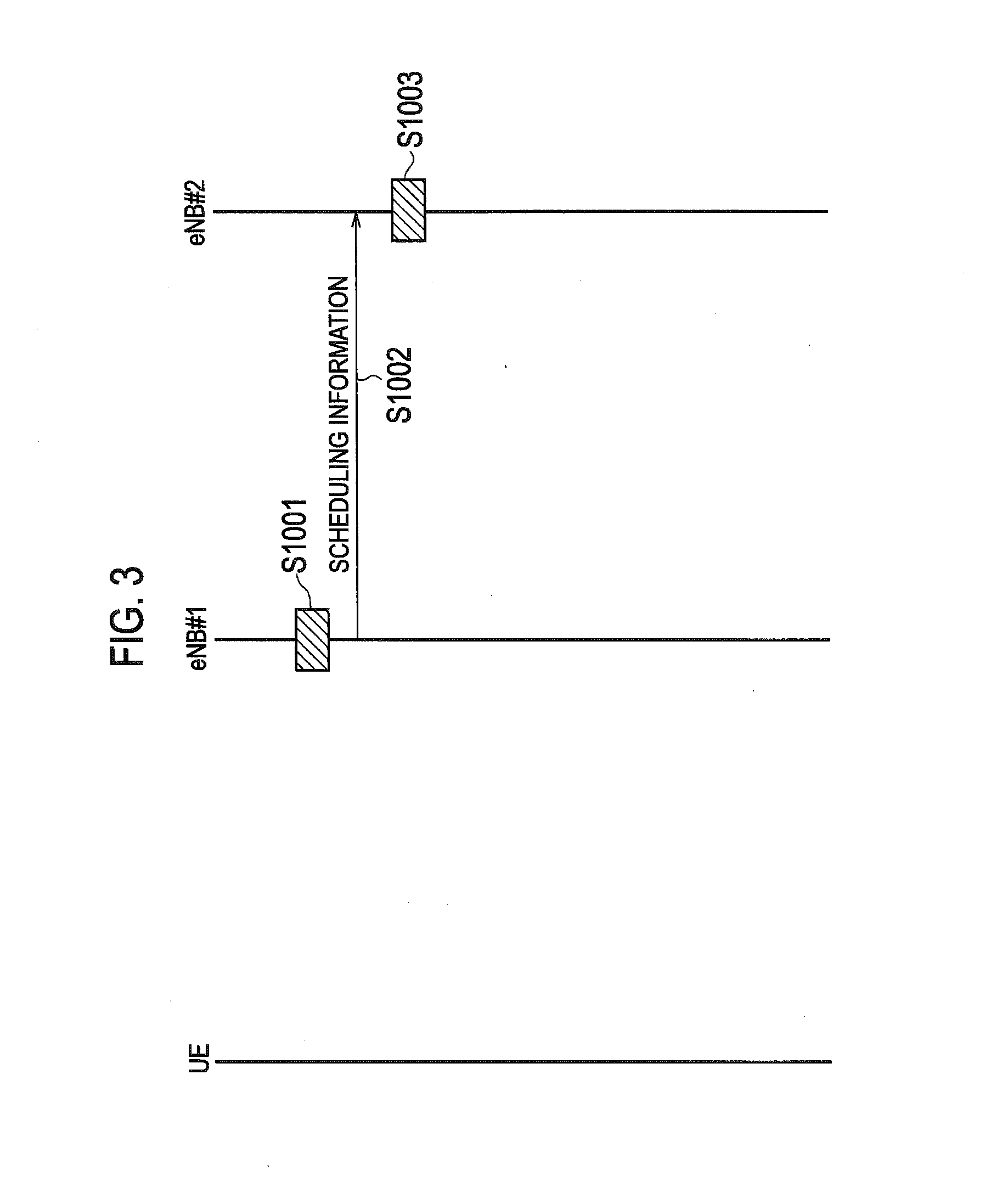
[0041]Referring now to FIGS. 3 to 5, a mobile communication system according to a second embodiment of the present invention will be explained below while focusing on the points of difference with the mobile communication system according to the first embodiment.
[0042]In the mobile communication system according to the present embodiment, the controlling unit 11 of the radio base station eNB#1 performs the scheduling control and the transmission power control on the mobile station UE in the cell #1 under the control of the radio base station eNB#1. The controlling unit 11 of the radio base station eNB#2 performs the scheduling control and the transmission power control on the mobile station UE in the cells #2A to #2C under the control of the radio base station eNB#2.
[0043]Moreover, in the mobile communication system according to the present embodiment, only one among the radio base stations eNB#1 and eNB#2 can perform the scheduling control on the mobile station ...
third embodiment
of Present Invention
[0064]Referring now to FIG. 6, a mobile communication system according to a third embodiment of the present invention will be explained below while focusing on the points of difference with the mobile communication systems according to the first and second embodiments of the present invention.
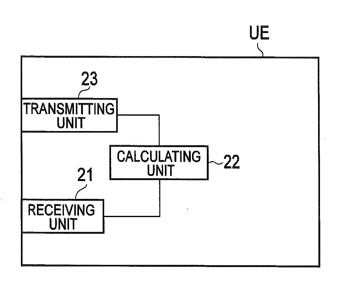
[0065]As shown in FIG. 6, a mobile station UE according to the present embodiment includes a receiving unit 21, a calculating unit 22, and a transmitting unit 23.
[0066]The receiving unit 21 receives various signals from the radio base stations eNB#1 and eNB#2, and the transmitting unit 23 transmits various signals to the radio base stations eNB#1 and eNB#2.
[0067]The calculating unit 22 calculates a change amount of a predetermined variable. The predetermined variable includes MPUSCH,C indicating the number of the resource blocks assigned to the mobile station UE in each of the cells #1 and #2A to #2C under the control of the plural radio base stations eNB#1 and eNB#2; the pr...
PUM
 Abstract
Description
Claims
Application Information
 - R&D Engineer
- R&D Manager
- IP Professional
- Industry Leading Data Capabilities
- Powerful AI technology
- Patent DNA Extraction
Browse by: Latest US Patents, China's latest patents, Technical Efficacy Thesaurus, Application Domain, Technology Topic.
© 2024 PatSnap. All rights reserved.Legal|Privacy policy|Modern Slavery Act Transparency Statement|Sitemap