
Tubing everting apparatus, assemblies, and methods

Active Publication Date: 2016-09-08
EMAGINEERED SOLUTIONS INC
View PDF1 Cites 4 Cited by
  • Summary
  • Abstract
  • Description
  • Claims
  • Application Information

AI Technical Summary

Benefits of technology

This patent describes an apparatus, assemblies, and methods for everting flexible tubing. The apparatus includes a pressure chamber, a liner inlet port, an inlet sealing structure, a liner outlet port, and a lubricator. The apparatus also includes a non-deflation valve that can control fluid flow through the liner. The methods involve using the apparatus to extend a flexible tube liner through the pressure chamber and attach it to the apparatus, while creating a seal to prevent fluid leakage. The apparatus can also include a cart for easy transport and a lubricant reservoir for lubricating the flexible tube liner. The technical effect of this invention is to provide a reliable and efficient way to ever flexible tubing in a controlled and safe manner.

Problems solved by technology

However, conventional tubing everting apparatus generally do not include a provision for convenient and / or automated lubrication of the flexible tube liner during the eversion process.
However conventional tubing everting apparatus generally do not include a provision to regulate and / or restrict this loss, especially after a tail end of the flexible tube liner has been conveyed through the conventional tubing everting apparatus.
However, conventional tubing everting apparatus often are not easily transportable and / or may require a significant amount of disassembly prior to transport and subsequent reassembly after transport.

Method used


Image

  • Tubing everting apparatus, assemblies, and methods
  • Tubing everting apparatus, assemblies, and methods
  • Tubing everting apparatus, assemblies, and methods

Examples


Embodiment Construction

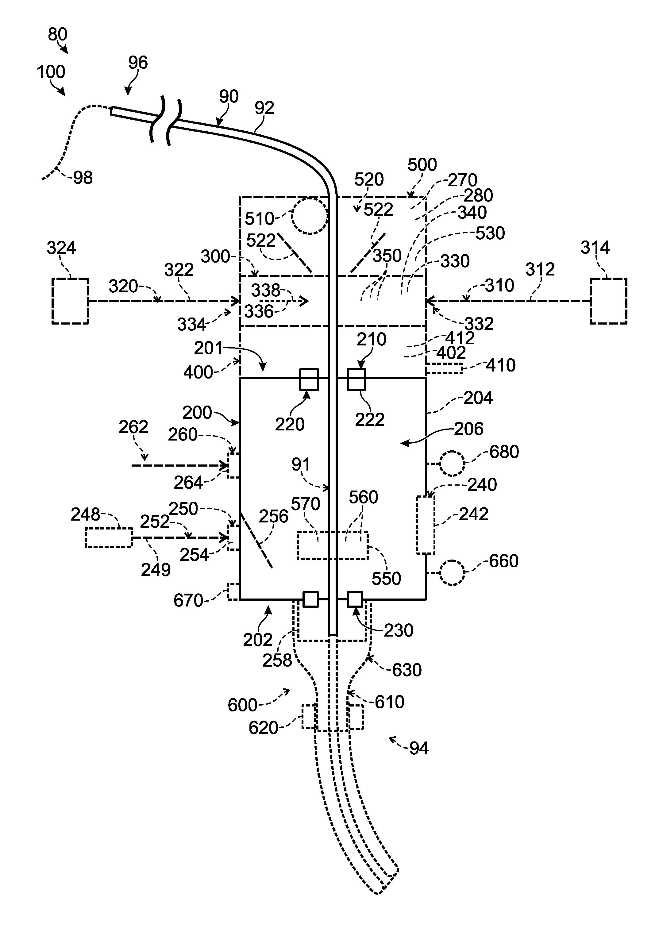
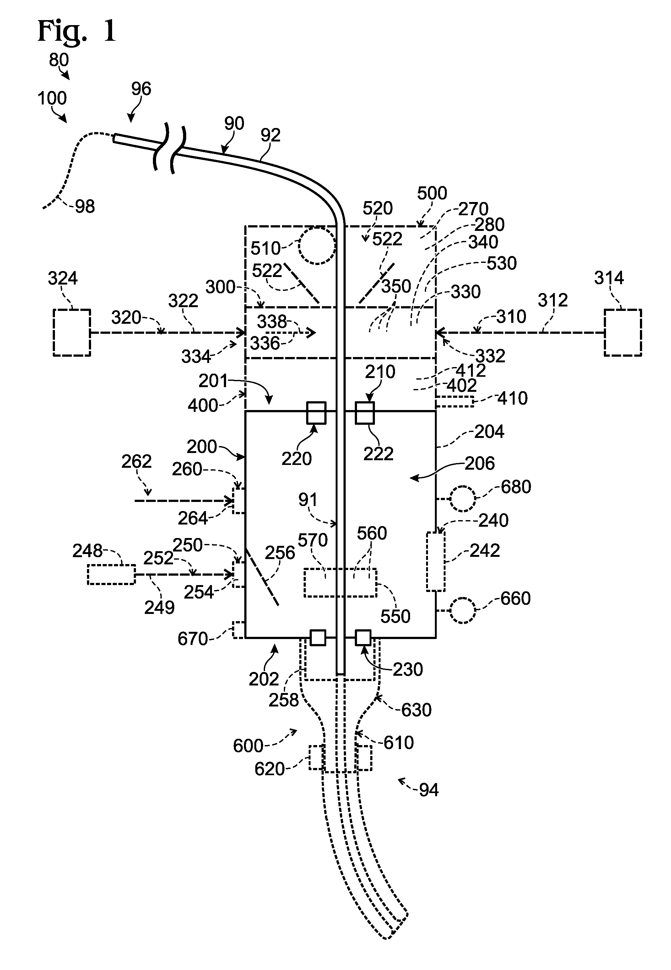
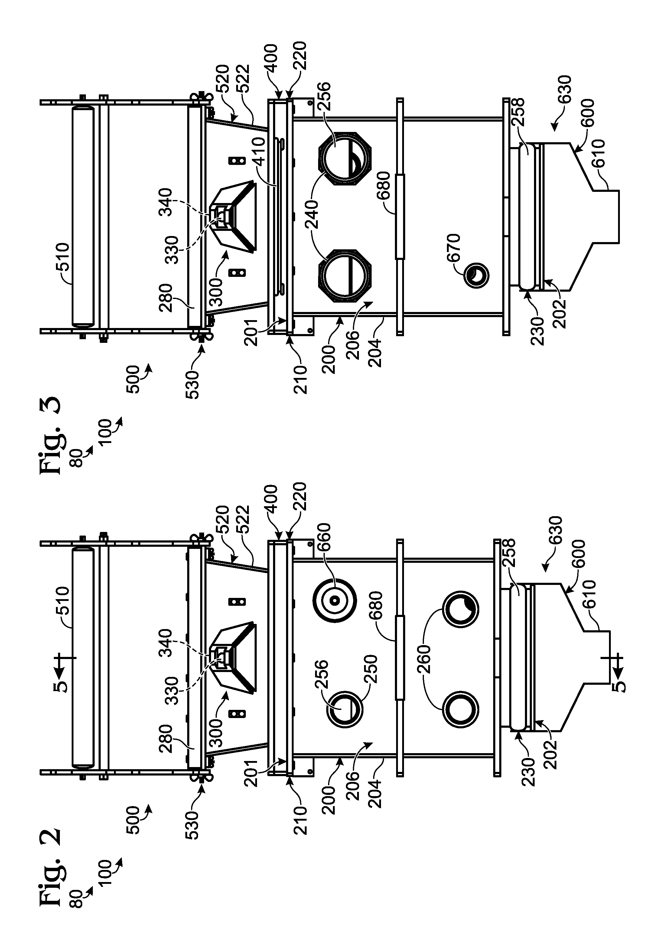
[0026]FIGS. 1-16 provide examples of tubing everting apparatus 100, according to the present disclosure, of carts 150, according to the present disclosure, of tubing everting assemblies 80 that include tubing everting apparatus 100 and / or carts 150, and / or of methods 800 of operating tubing everting assemblies 80 and / or tubing everting apparatus 100. Elements that serve a similar, or at least substantially similar, purpose are labeled with like numbers in each of FIGS. 1-16, and these elements may not be discussed in detail herein with reference to each of FIGS. 1-16. Similarly, all elements may not be labeled in each of FIGS. 1-16, but reference numerals associated therewith may be utilized herein for consistency. Elements, components, and / or features that are discussed herein with reference to one or more of FIGS. 1-16 may be included in and / or utilized with any of FIGS. 1-16 without departing from the scope of the present disclosure. In general, elements that are likely to be inc...


PUM

PropertyMeasurementUnit
Pressureaaaaaaaaaa
Flexibilityaaaaaaaaaa
Frictional forceaaaaaaaaaa

Abstract

Tubing everting apparatus, assemblies, and methods are disclosed herein. The tubing everting apparatus include a pressure chamber that defines an internal volume, a liner inlet port that is configured to receive a flexible tube liner into the internal volume, an inlet sealing structure that is configured to resist fluid flow therepast from the pressure chamber, and a liner outlet port that is configured to permit the flexible tube liner to extend from the internal volume. In some embodiments, the apparatus include a lubricator that is configured to apply a lubricant to the flexible tube liner. In some embodiments, the apparatus include a non-deflation valve that is configured to selectively transition between open and closed states. The assemblies include the apparatus and a cart that includes a lubricant reservoir. The methods include methods of operating the apparatus.

Description

RELATED APPLICATION[0001]This application claims priority to U.S. Provisional Patent Application No. 62 / 128,107, which was filed on Mar. 4, 2015, and the complete disclosure of which is hereby incorporated by reference.FIELD OF THE DISCLOSURE[0002]The present disclosure relates generally to tubing everting apparatus, assemblies, and methods.BACKGROUND OF THE DISCLOSURE[0003]A tubing everting apparatus may be utilized to line an existing tubular, such as a pipe, a drain pipe, and / or a sewer pipe, with a flexible tube liner. The flexible tube liner subsequently may be cured in place within the existing tubular to at least substantially fix a conformation of the flexible tube liner and / or to resist subsequent deformation of the flexible tube liner. Such a process may be utilized to repair and / or rehabilitate existing tubulars that may be broken, cracked, and / or damaged, thereby decreasing and / or eliminating fluid leakage and / or infiltration from the existing tubular. Additionally or al...

Claims


Application Information

Patent Timeline
IPC IPC(8): F16L55/165F16L55/18
CPCF16L55/18F16L55/1651B29C63/36E03F2003/065
Inventor WARING, STEPHEN T.HUCKFELDT, ROSSEN ROBERT
Owner EMAGINEERED SOLUTIONS INC
Learn More