Autonomous emergency braking system and method of controlling the same

a technology of emergency braking and automatic braking, which is applied in the direction of braking systems, pedestrian/occupant safety arrangements, vehicular safety arrangements, etc., can solve the problems of excessive braking, pedestrians may be unnecessarily startled, and it is difficult to quickly brake a vehicle, so as to reduce the necessary braking level

Active Publication Date: 2016-09-22
HL KLEMOVE CORP
View PDF5 Cites 41 Cited by
  • Summary
  • Abstract
  • Description
  • Claims
  • Application Information

AI Technical Summary

Benefits of technology

The invention relates to an electronic control system for vehicles that can detect if there is a person walking near the vehicle and adjust its brakes accordingly to prevent hitting them. The system uses sensors to predict where the person will be located and reduces the amount of force needed to stop or slow down the car based on this prediction. This technology helps improve safety while driving and avoids accidents with people who are trying to cross the road.

Problems solved by technology

The technical problem addressed in this patent text is the difficulty for drivers with limited response time to quickly brake a vehicle and the potential for unnecessary startling or excessive braking of pedestrians when using autonomous emergency braking systems.

Method used


Image

  • Autonomous emergency braking system and method of controlling the same
  • Autonomous emergency braking system and method of controlling the same
  • Autonomous emergency braking system and method of controlling the same

Examples


Embodiment Construction

[0029]Hereinafter, exemplary embodiments of the present invention will be described in detail with reference to the attached drawings. The embodiments which will be described below are provided as an example to allow one of ordinary skill in the art to fully understand the concept of the present invention. The present invention is not limited to the embodiments described below and may be embodied in other forms. To clearly describe the present invention, a part irrelevant to the description will be omitted in the drawings. Throughout the drawings, a width, length, and thickness of a component may be exaggerated for convenience of description. Like reference numerals designate like elements throughout.

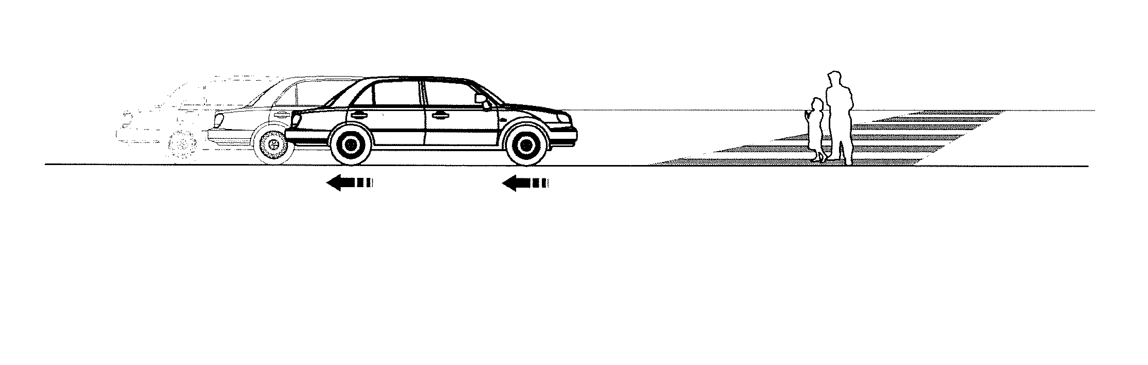
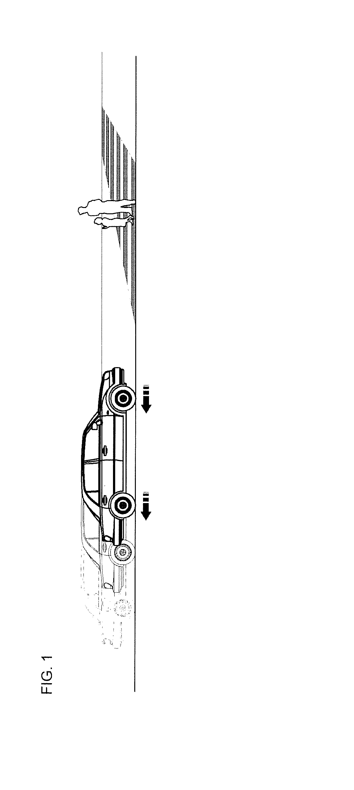
[0030]FIG. 1 is a configuration diagram illustrating control of autonomous emergency braking in a warning area and a braking area of an autonomous emergency braking system in accordance with one embodiment of the present invention.

[0031]Referring to FIG. 1, the autonomous emergency brak...


PUM


Abstract

Disclosed herein are an autonomous emergency braking system and a method of controlling the same. The autonomous emergency braking system includes a vehicle speed detector, a pedestrian position detector, a pedestrian information storage portion and an electronic control unit which, when the position of the pedestrian detected by the pedestrian position detector is located in a warning area or a braking area in front of the vehicle, receives the vehicle speed and information of the position of the pedestrian detected by the pedestrian position detector, calculates a time to collision (TTC), predicts a relative position of the pedestrian compared with the vehicle at a point in time after the calculated TTC passes by tracking a moving trajectory of the pedestrian from a time series change in the position of the pedestrian stored in the pedestrian information storage portion, and performs autonomous emergency braking control depending on the predicted relative position of the pedestrian.

Description


Claims


Application Information

Patent Timeline
Owner HL KLEMOVE CORP
Why Eureka
Try Eureka