
Loudspeaker assembly with suppression of magnetic flux modulation distortion
a loudspeaker and magnetic flux technology, applied in the field of electrodynamic loudspeaker assembly, can solve the problems of magnetic flux modulation, source of distortion artifacts in the reproduced sound, and inability to effectively cancel magnetic flux modulation across any significant audio frequency range, and achieve the effect of suppressing magnetic flux modulation
- Summary
- Abstract
- Description
- Claims
- Application Information
AI Technical Summary
Benefits of technology
Problems solved by technology
Method used
Image

Examples
Embodiment Construction
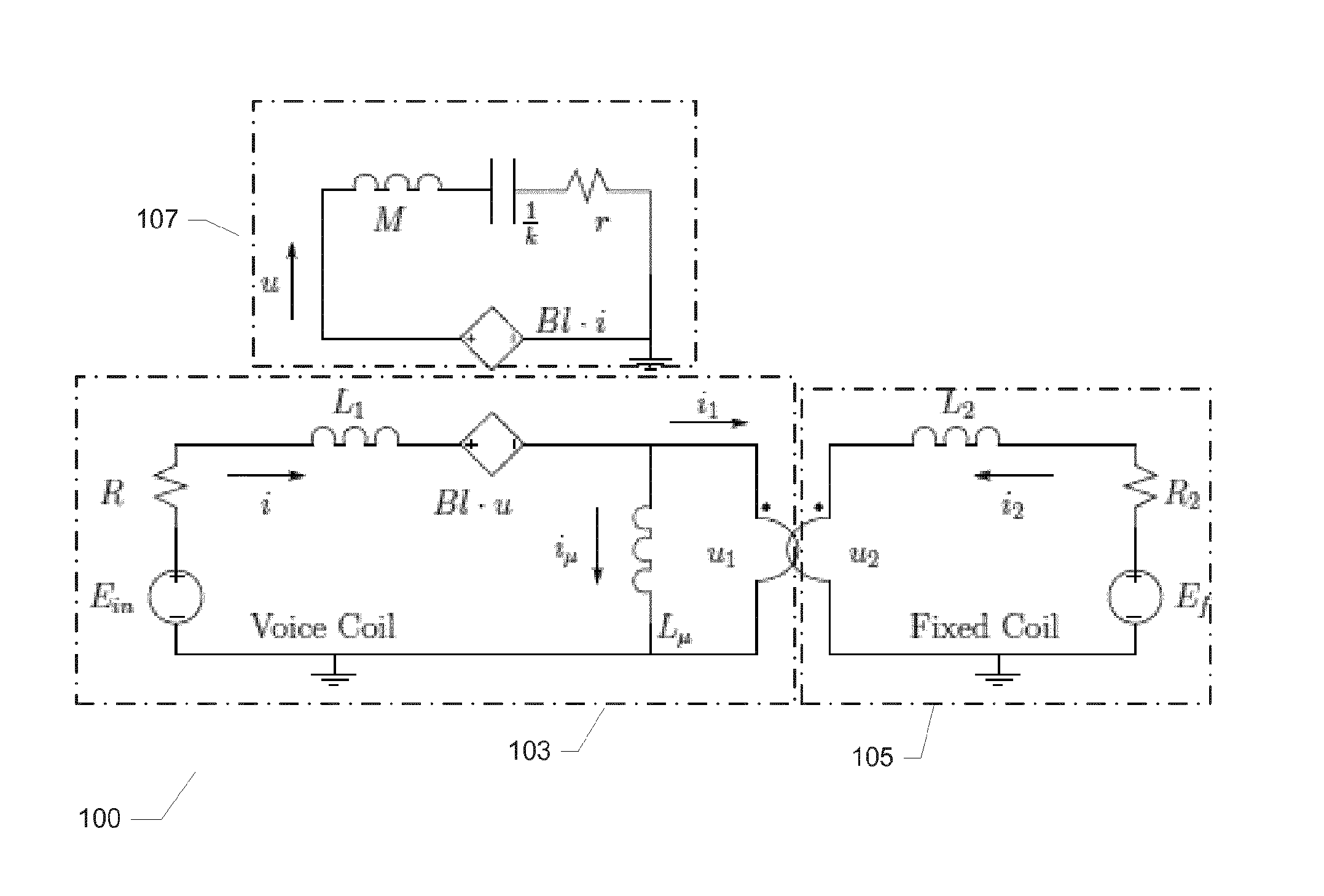
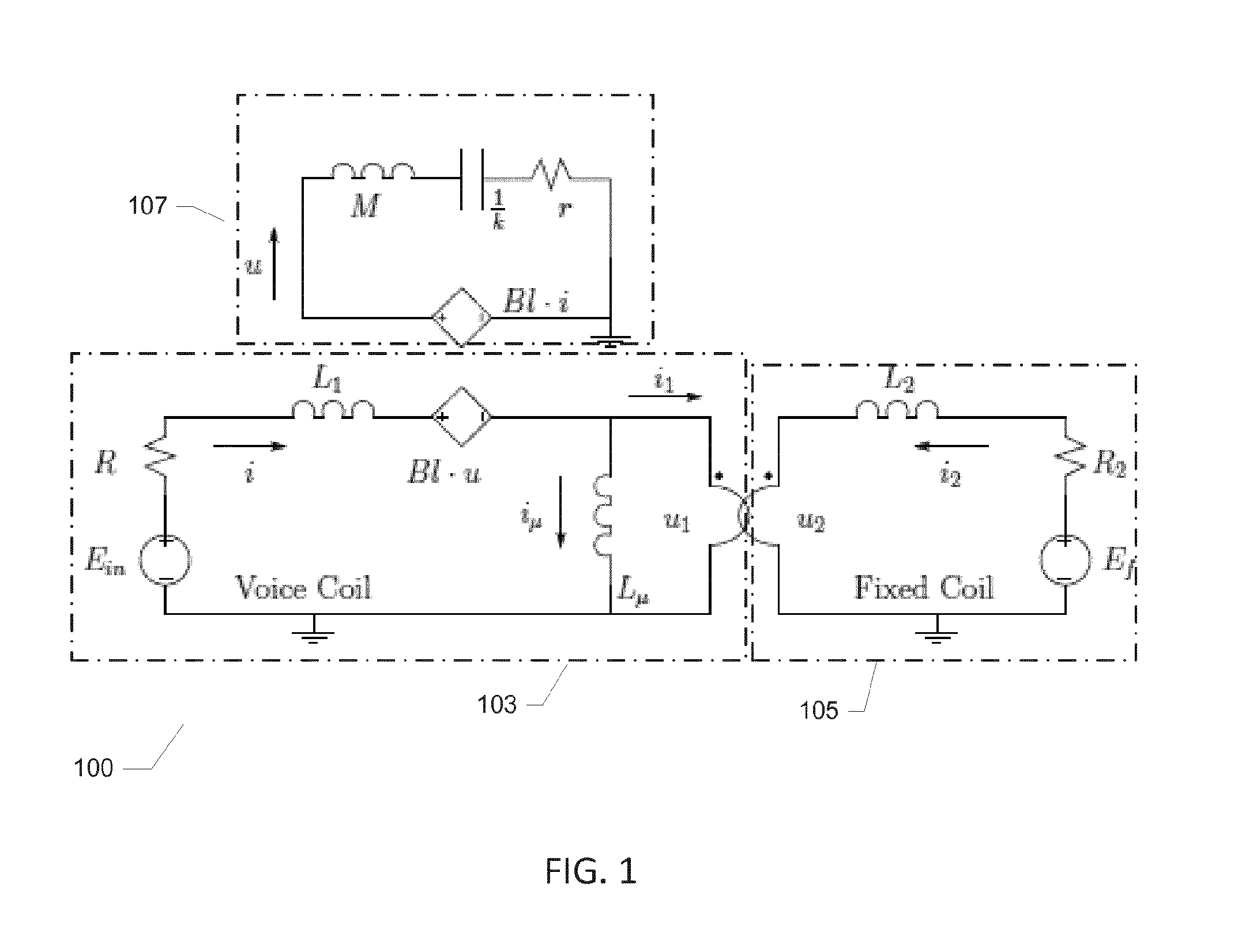
[0056]FIG. 1 is a schematic electrical equivalent diagram 100 of an electrodynamic loudspeaker comprising a fixed or compensation coil suitable as a component of the below discussed loudspeaker assembly in accordance with a first embodiment of the invention. Notice that in the following description for simplicity the permanent magnet of the loudspeaker will be replaced by supplying the compensation or fixed coil with a DC current which represent the magnetomotive force of a permanent magnet in a magnetic circuit of the loudspeaker. As illustrated on the drawing, the voice coil impedance of the voice coil equivalent circuit 103 is modeled by a resistor R, an inductance L1, a back-emf due to the mechanical system BI*u—so far an ordinary model of a normal loudspeaker—in series with a transformer that connects the voice coil to the compensation coil. The compensation coil of the compensation coil equivalent circuit 105 has a similar impedance with a resistor R2 and an inductance L2. The...
PUM
 Abstract
Description
Claims
Application Information