
Vibratory shaker screen assembly

a vibrating shaker and assembly technology, applied in the direction of screening, solid separation, chemistry apparatus and processes, etc., can solve the problems of other components of the vibrating shaker screen, failure of often occurring,

Inactive Publication Date: 2016-10-06
CONTINENTAL WIRE CLOTH LLC
View PDF14 Cites 5 Cited by
  • Summary
  • Abstract
  • Description
  • Claims
  • Application Information

AI Technical Summary

Benefits of technology

The invention is a shaker screen that consists of a frame and a screen attached to the frame. The frame has a top surface, a bottom surface, and a sidewall that connects the top and bottom surfaces. The sidewall has an inside and outside surface. A gasket is attached to the frame, with one portion attached to the bottom surface and another portion attached to the inside surface of the sidewall. The technical effect of this invention is to provide a more secure and effective attachment of the screen to the frame, which improves the overall performance of the shaker screen.

Problems solved by technology

Such a failure often occurs well before other components of the shaker screen 20 fail.

Method used


Image

  • Vibratory shaker screen assembly
  • Vibratory shaker screen assembly
  • Vibratory shaker screen assembly

Examples


Embodiment Construction

[0025]As used herein and in the appended claims, a shaker machine refers to a vibratory shaker machine. A shaker screen refers to a vibratory shaker screen assembly for use in connection with a shaker machine to separate solids from a mixture of solids and liquids.

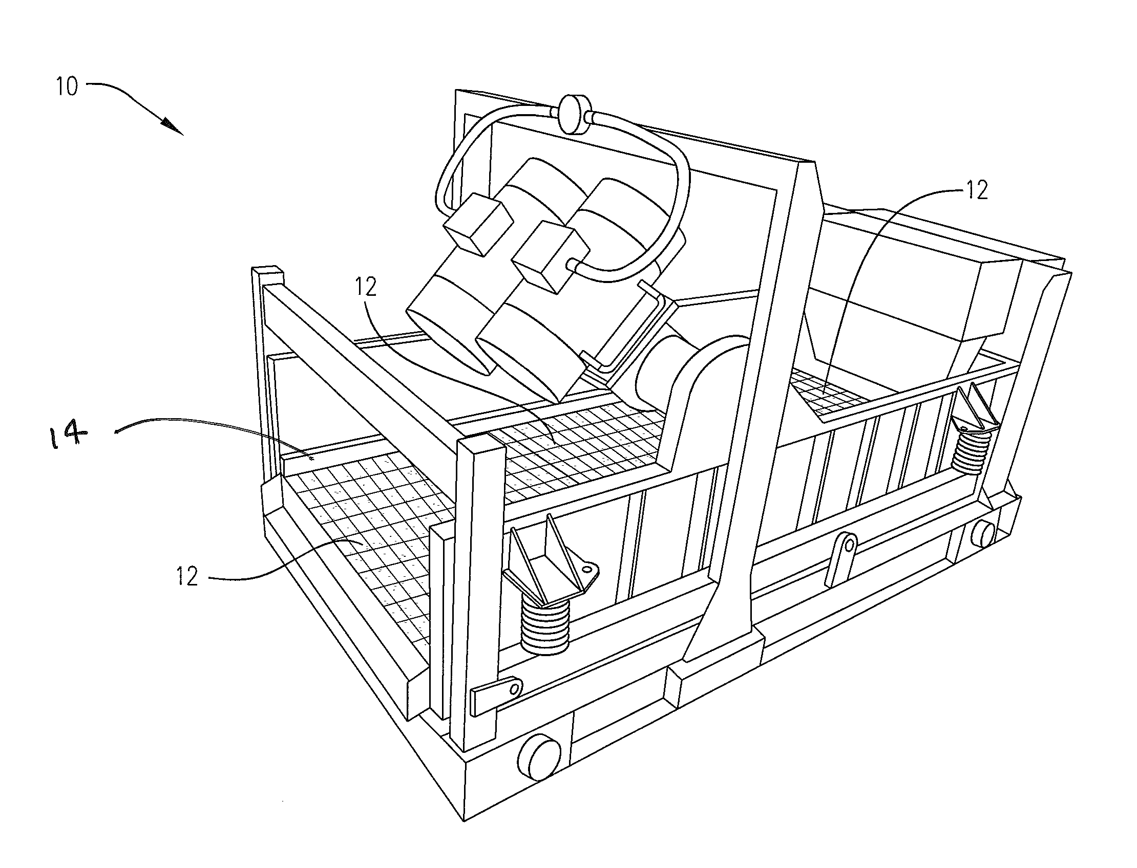
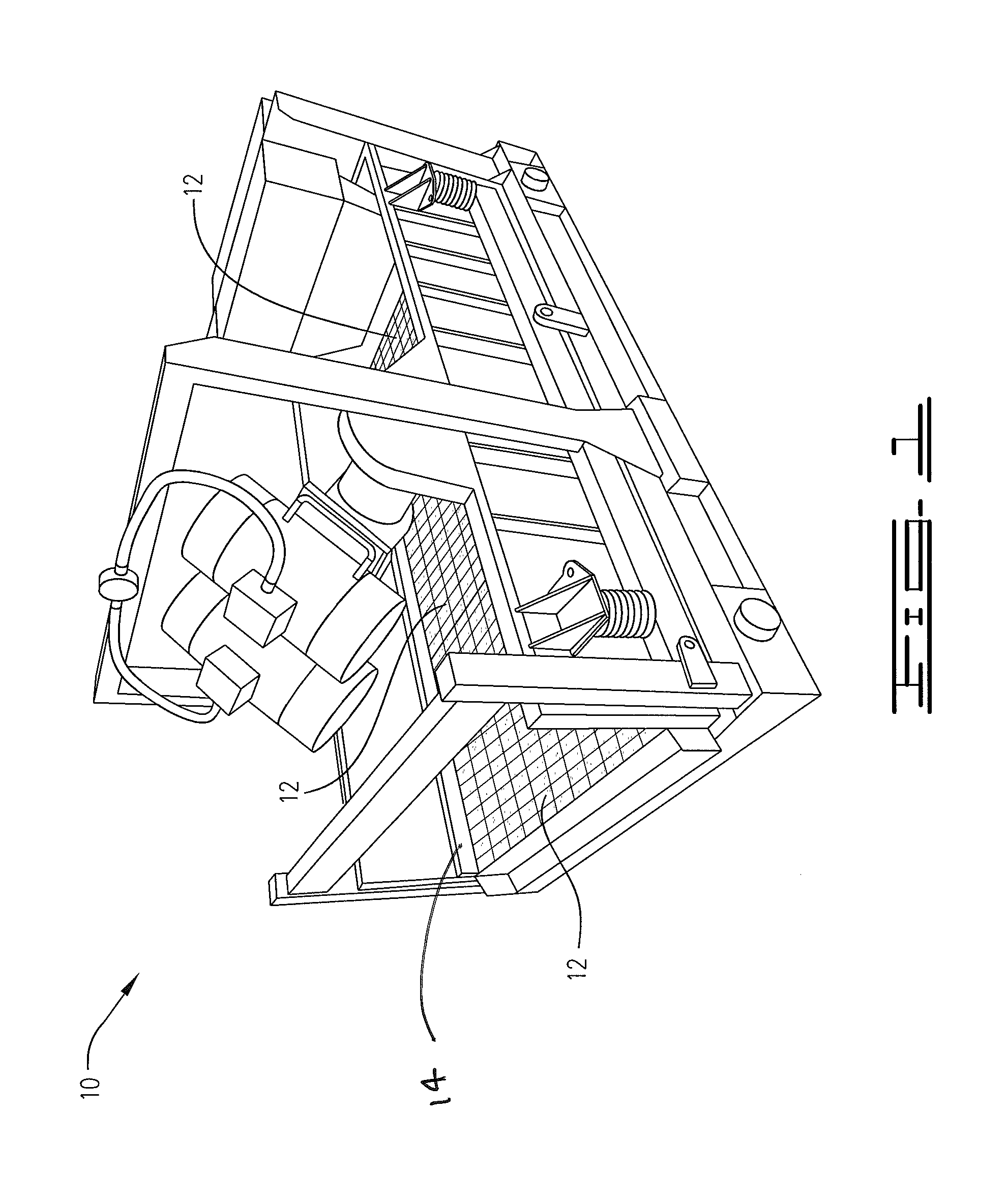
[0026]Referring to FIG. 1, a typical shaker machine is described and generally designated by the reference number 10. In this machine, three shaker screens 12, each being identical in shape and size, are attached side by side to the shaker machine 10. The shaker screens 12 are attached to the shaker machine by flanges or wedges 14.

Prior Art Shaker Screen

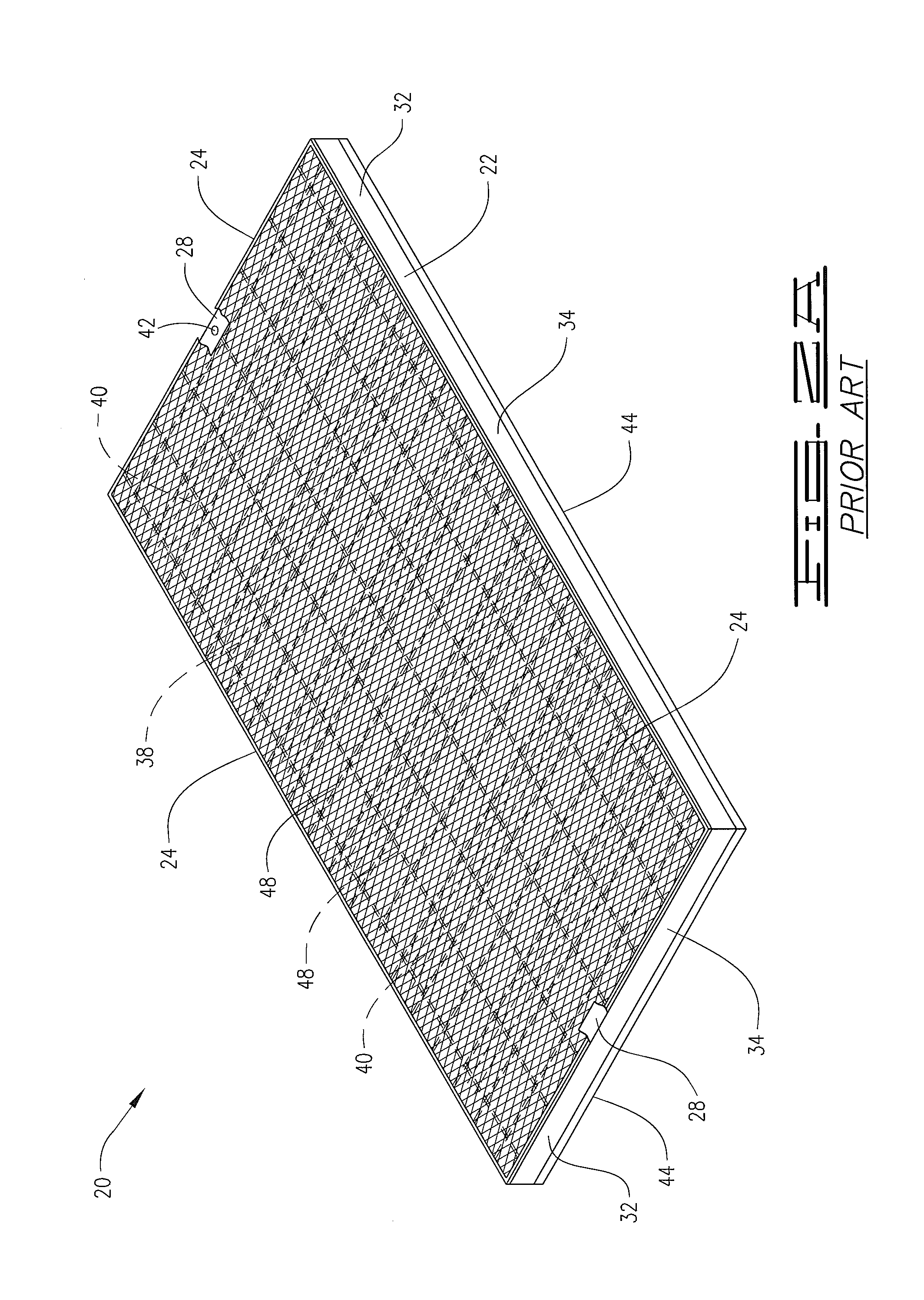
[0027]Referring now to FIGS. 2A and 2B, a shaker screen known in the art is described and generally designated by the reference number 20. The shaker screen 20 comprises a frame 22 and a screen subassembly 24 attached to the frame.

[0028]The frame 22 includes a top surface 28, a bottom surface 30, and a sidewall 32 connecting the top surface and bottom surface together. The ...


PUM


Abstract

A shaker screen comprising a frame and a screen member attached to the frame is provided. The frame has a top surface, a bottom surface, and a sidewall connecting the top surface and bottom surface together. The sidewall has an outside surface and an inside surface. A gasket is attached to the frame, the gasket having a first portion attached to the bottom surface of the frame and a second portion attached to a surface of the sidewall of the frame.

Description

BACKGROUND[0001]A vibratory shaker machine, sometimes referred to as a shale shaker or mud shaker (hereafter a “shaker machine”), is used in the oil and gas industry and other industries to separate solids from a mixture of solids and liquids. For example, shaker machines are commonly used in processes to reclaim used oil and gas well drilling mud to separate cuttings, rock and other solid particles from the mud.[0002]In operating a shaker machine, the mixture of solids and liquids is caused to flow onto and through a vibratory shaker screen assembly (hereafter a “shaker screen”), which is removably attached to the shaker machine and functions to filters solids from the liquid. In order to facilitate the filtration process and cause the separated solids to slide off the top of the shaker screen, the shaker screen is caused to vibrate by the shaker machine. Usually, two or more shaker screens are positioned side by side on the shaker machine.[0003]A typical shaker screen includes one...

Claims


Application Information

Patent Timeline
IPC IPC(8): B07B1/46
CPCB07B1/46B07B1/4609B07B1/4618B07B1/4663
Inventor BISSETT, JAMES R.
Owner CONTINENTAL WIRE CLOTH LLC
Learn More