Deflectable Catheter Bodies with Corrugated Tubular Structures

a catheter body and tubular structure technology, applied in the direction of catheters, other domestic objects, surgery, etc., can solve the problems of not being able to systematically and synergistically consider axial curvatures, and achieve different degrees of rigidity, flexibility or hardness, and different melting or softening temperatures

Active Publication Date: 2016-11-03
ST JUDE MEDICAL CARDILOGY DIV INC
View PDF10 Cites 11 Cited by
  • Summary
  • Abstract
  • Description
  • Claims
  • Application Information

AI Technical Summary

Benefits of technology

[0010]The deflectable bodies may be axially comprised of two corrugate tubes which can be converted to intimately bonded and interlocked-in-place tubular structures after manufacture. The corrugation may comprise a plurality of peaks 40 and troughs 41, also referred to as radial ridges and troughs or valleys. The two corrugate tubes or layers for each deflectable body may be made of chemically compatible thermoplastic elastomer materials. In some embodiments, the corrugate tubes have different degrees of stiffness, flexibility or hardness. In addition, the corrugate tubes may have different melting or softening temperatures. The melting point of the first layer may differ from the melting point of the second layer by 20-30 degrees. In some embodiments, the first layer is Polyamide 12 and the second layer is a poly(ether block amide) copolymer. In at least one embodiment, the melting point of the first layer is greater than the melting point of the second layer. In at least one embodiment, the melting point of the first layer is less than the melting point of the second layer.

Problems solved by technology

Difficulties with the aforementioned catheters include failing to systematically and synergistically consider axial curvatures, deflection easiness, deflection in-planarity, and elastic recovery after deflection.

Method used


Image

  • Deflectable Catheter Bodies with Corrugated Tubular Structures
  • Deflectable Catheter Bodies with Corrugated Tubular Structures
  • Deflectable Catheter Bodies with Corrugated Tubular Structures

Examples


Embodiment Construction

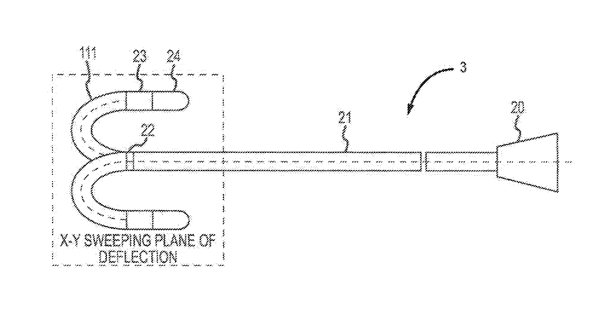
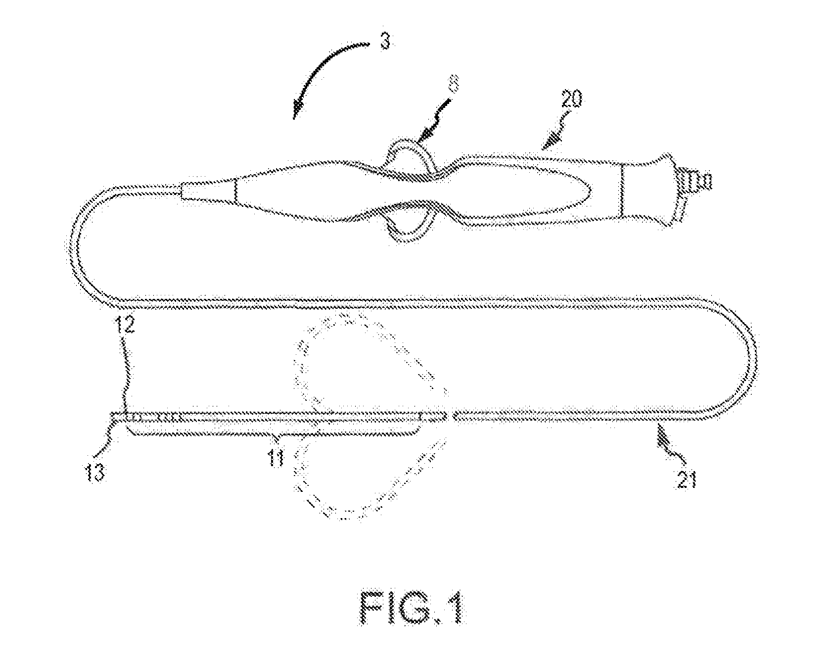
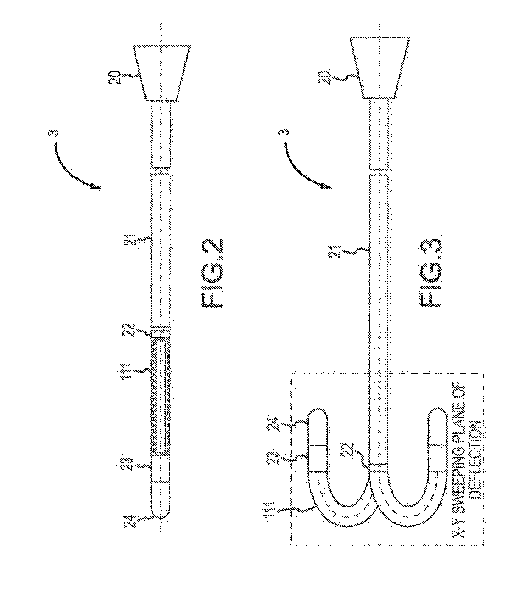
[0022]Various embodiments are described herein of various apparatuses, systems, and / or methods. Numerous specific details are set forth to provide a thorough understanding of the overall structure, function, manufacture, and use of the embodiments as described in the specification and illustrated in the accompanying drawings. It will be understood by those skilled in the art, however, that the embodiments may be practiced without such specific details. In other instances, well-known operations, components, and elements have not been described in detail so as not to obscure the embodiments described in the specification. Those of ordinary skill in the art will understand that the embodiments described and illustrated herein are non-limiting examples, and thus it can be appreciated that the specific structural and functional details disclosed herein may be representative and do not necessarily limit the scope of the embodiments, the scope of which is defined solely by the appended cla...


PUM

PropertyMeasurementUnit
) temperatureaaaaaaaaaa
melting temperatureaaaaaaaaaa

Abstract

A guidable, or steerable, or deflectable catheter is provided that includes a proximal portion and a distal portion for insertion into a body cavity. A selectively deflectable segment having an anisotropic bending stiffness for deflection in individual planes is incorporated into the distal portion of the catheter shaft. The deflectable segment comprises a corrugate structure that provides smooth curvatures of desirable configurations, deflection planarity, and easiness.

Description

BACKGROUND[0001]The instant disclosure relates to deflectable and steerable elongate devices, such as medical catheters. In particular, the instant disclosure relates to catheters having segments with anisotropic deflecting or bending stiffness that reduce or eliminate unintended out-of-plane movement of the catheter.[0002]Deflectable and steerable elongate devices such as catheters are used for an ever-growing number of medical, industrial, and manufacturing procedures. For example, catheters are used for diagnostic, therapeutic, and ablative procedures. During these procedures, a catheter is typically inserted into a vessel near the surface of the body and is guided to a specific location within the body for examination, diagnosis, and treatment. A catheter typically carries one or more energy emitting elements (e.g., electrodes, hyperthermic ablation elements, cryogenic elements, etc.), which may be used for tissue ablation, diagnosis, or the like. Some catheters perform only pas...

Claims


Application Information

Patent Timeline
Patent Type & Authority Applications(United States)
IPC IPC(8): A61B18/14A61M25/00B29C65/02A61M25/01
CPCA61B18/1492A61M25/0147A61M25/005B29L2031/7542B29C65/02A61B2018/00351B29K2077/00A61M25/0009A61M25/0045A61B2018/00357
Inventor GUO, XIAOPING
Owner ST JUDE MEDICAL CARDILOGY DIV INC
Why Eureka
Try Eureka