Servicing of landing gear shock absorbers

a technology for landing gear shock absorbers and shock absorbers, which is applied in the direction of shock absorbers, instruments, final product manufacturing, etc., can solve the problems of inaccurate determination, underestimate the amount of gas contained in the shock absorber, and underestimate the pressure of the gas

Active Publication Date: 2017-01-12
AIRBUS OPERATIONS LTD
View PDF2 Cites 24 Cited by
  • Summary
  • Abstract
  • Description
  • Claims
  • Application Information

AI Technical Summary

Benefits of technology

[0019]It may be that a collar is arranged around the landing gear assembly, the collar bearing at least some of the load that would otherwise be sustained by the shock absorber. The collar may thus perform the function of a stop. The collar may assist in the supporting, at least in part, of the weight of the aircraft. The step of arranging such a stop, or collar, may be conducted before the step of exhausting all gas from the chamber is completed. The step of arranging such a stop, or collar, may be conducted before the step of exhausting the gas from the chamber is started. The collar may extend more than 180 degrees around the shock absorber.

Problems solved by technology

Taking into account the pressure, temperature, and volume of the gas (not contained within the hydraulic fluid), in the weight on wheels state, without considering the amount of gas contained within the hydraulic fluid (whether dissolved, suspended as bubbles of gas in the liquid, or otherwise contained) will not provide a very accurate determination of the sum total of mass of gas within the shock absorber and could provide underestimates of the amount of gas that is contained in the shock absorber and therefore underestimates of the pressure of the gas that will be in the gaseous state for a given temperature and volume in the shock absorber immediately before landing.
In certain methods of the prior art, a less than expected H-dimension would be interpreted only as a lack of gas, leading to the replacement of lost hydraulic fluid and / or absorbed gas with additional gas, most probably leading to inaccurate servicing of the shock absorber.
Also, in such prior art methods, if adding more gas whilst the shock absorber is under pressure (in a weight on wheels configuration for example) no account would be taken of the absorption of gas during the pressurisation process, also leading to greater potential inaccuracies.

Method used


Image

  • Servicing of landing gear shock absorbers
  • Servicing of landing gear shock absorbers
  • Servicing of landing gear shock absorbers

Examples


first embodiment

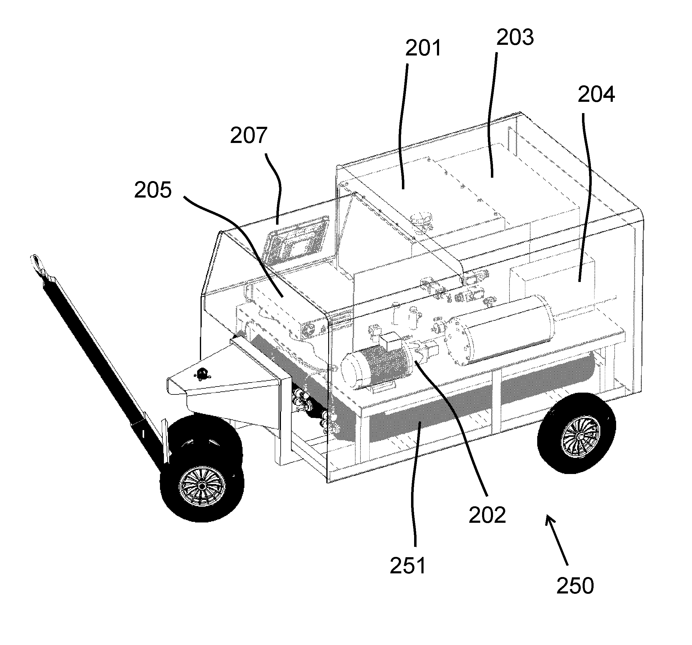
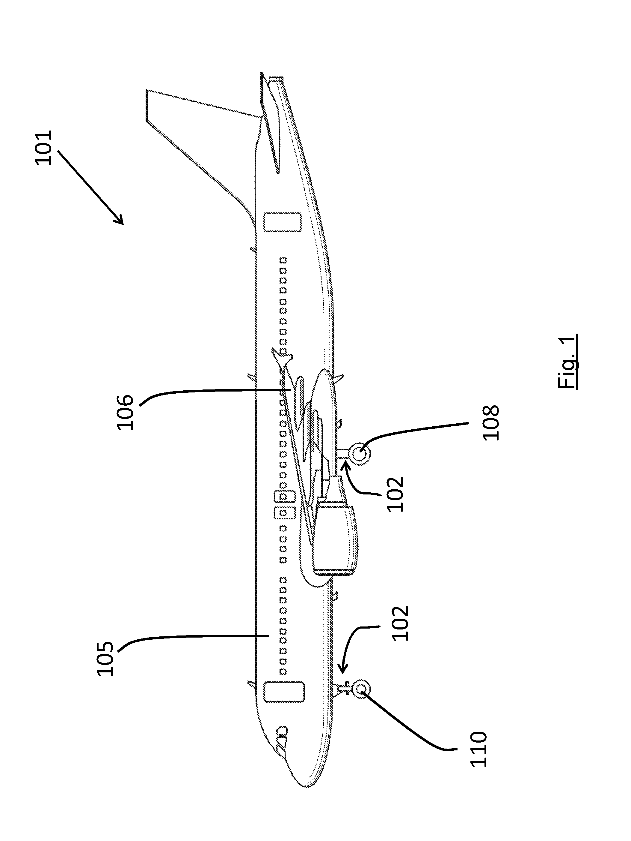
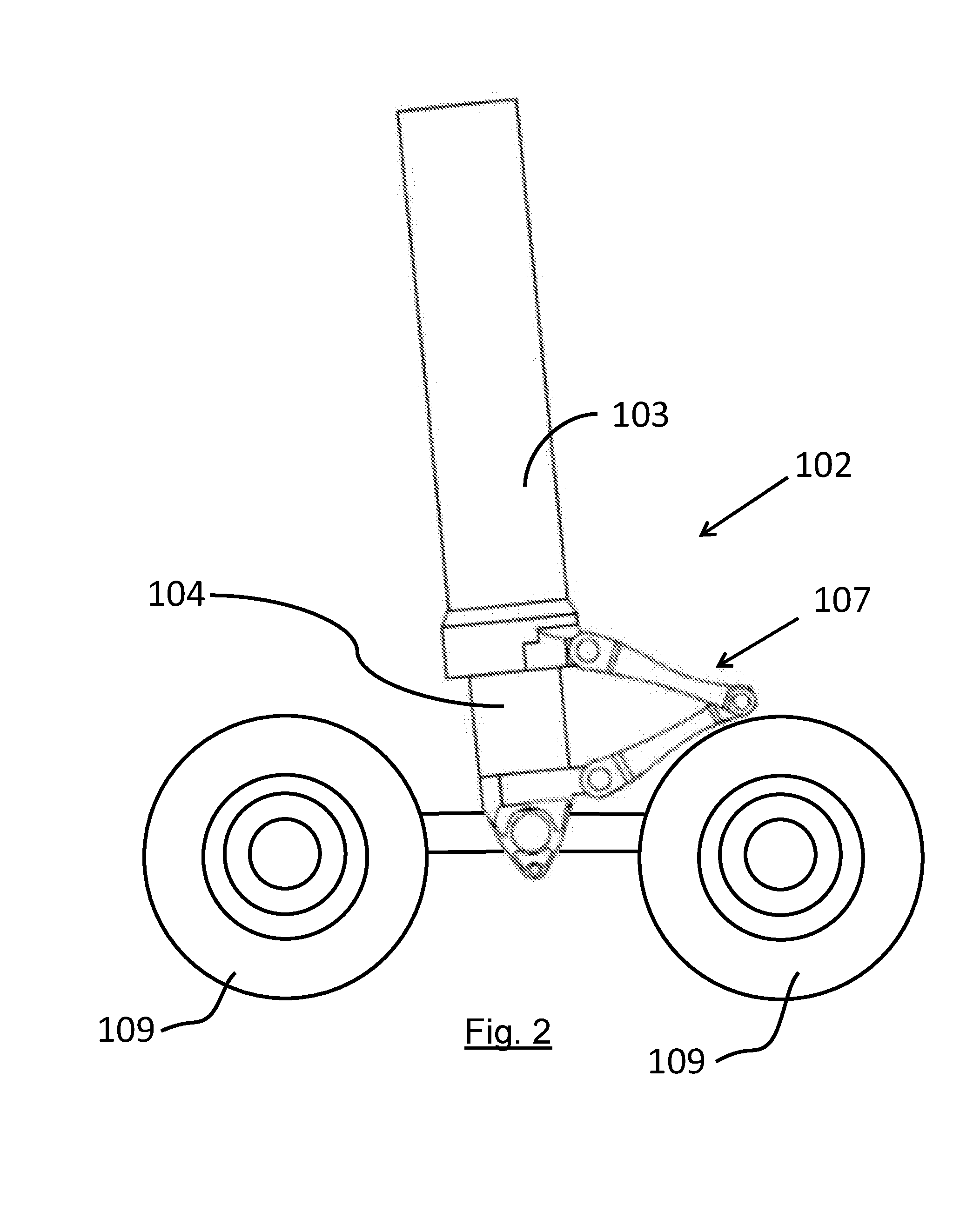
[0072]the present invention concerns servicing of an aircraft landing gear shock absorber 102 with the use of a lightweight portable servicing cart 117. The cart 117 is shown in FIGS. 5a and 5b and comprises two primary parts, a deflation kit 118 (see FIG. 6) and an inflation kit 119 (see FIG. 7). The main components of the deflation kit 118 (referred to below as the Deflation and Oil Replenishment Tool or “DORT”) are a vacuum pump 129, a hydraulic fluid trap 126 and a source 128 of hydraulic fluid. The main components of the inflation kit are pressurised canisters of N2 120 (supplied separately from the cart 117 shown in FIGS. 5a and 5b), and a gas delivery system including a control unit 136.

[0073]FIG. 6 shows the “DORT” deflation kit 118 attached to a shock absorber 102. There is included a quick release coupling 123 for connection to the shock absorber 102 via a hose 122. A gas vent 130 is connected via valves 125 and 127 and a fluid trap 126 to quick release coupling 123. Also ...

second embodiment

[0112]A method of servicing a shock absorber 102 using the portable servicing cart 250 of the second embodiment will now be described.

[0113]The semi-automatic process includes both manual steps (represented by box 320) conducted before and after an otherwise automatic process (represented by box 310). At the start 321 of the servicing process, the operator of the cart inputs details of the gear into the Human-Machine-Interface (HMI) 207, attaches the supporting collar 5 to the gear, and connects the two hoses to the shock absorber charge valves 114, 115. These steps are represented by box 322 in FIG. 12. The operator then opens the charge valves (step 323) and then presses the ‘Start’ button (step 324) on the Human-Machine-Interface 207 to begin the automatic service process (represented by box 310). The system then automatically services the shock absorber in accordance with the steps described below (and illustrated in FIG. 12). It will be appreciated that Steps 1 and 6 are not ap...


PUM


Abstract

A method and portable apparatus for servicing a shock absorber on a landing gear assembly of an aircraft in a weight-on-wheels state is disclosed. The shock absorber includes at least one chamber containing both hydraulic fluid and a gas in fluid communication with each other. The apparatus includes a source of gas and a source of hydraulic fluid. The amount of hydraulic fluid in the chamber is corrected, preferably such that the chamber is then filled with a known amount of degassed hydraulic fluid. A pre-set mass of gas is then delivered into the chamber under the control of a gas delivery system of the portable apparatus. More accurate servicing of a shock absorber may thus be provided since account is additionally taken of gas dissolved in hydraulic fluid. By delivering a pre-set mass of gas into the chamber, there is no need to rely on a measure of gas pressure or H-dimension (h) when servicing the shock absorber.

Description

BACKGROUND OF THE INVENTION[0001]The present invention concerns the servicing of aircraft landing gear shock absorbers. More particularly, but not exclusively, this invention concerns a method of servicing a shock absorber on a landing gear assembly of an aircraft, and an apparatus for servicing such a shock absorber. The invention also concerns an associated control unit for use in such a method or apparatus and an associated computer program product.[0002]Aircraft landing gear assemblies typically include a shock absorber assembly (for example of the type referred to as an oleo strut) which provides suspension and shock absorbing functions for the aircraft during landing and take-off An aircraft 101 including such shock absorber assemblies 102 is shown in FIG. 1. A single such shock absorber assembly 102 is shown in greater detail in FIG. 2 together with a schematic illustration of the wheels 109. (Parts of the landing gear including, for example, the axles for mounting the wheels...

Claims


Application Information

Patent Timeline
Patent Type & Authority Applications(United States)
IPC IPC(8): B64F5/00B64C25/60F16F9/32
CPCB64F5/0081B64C25/60F16F9/3271B64D45/0005F16F9/3264G01M17/007G01M17/013G01M17/02G01M17/04B64F5/60B64F5/40Y02P70/50B64C25/58B64F5/00
Inventor POUNTNEY, OLIVERSHEPHERD, ALAN
Owner AIRBUS OPERATIONS LTD
Why Eureka
Try Eureka