Method and apparatus for manufacturing laminated iron core

Active Publication Date: 2017-01-12
MITSUI HIGH TEC INC
View PDF2 Cites 1 Cited by
  • Summary
  • Abstract
  • Description
  • Claims
  • Application Information

AI Technical Summary

Benefits of technology

The present invention provides a method and apparatus for manufacturing laminated iron cores that can prevent defective products from occurring. The method involves separating multiple block iron cores and rotating and laminating each one individually, without mistaking their order of lamination or angle of rotation. This prevents assembly line defects from occurring. Further, the method allows for efficient use of space by arranging the individual block iron cores on a rotating placement table. This allows for sequential movement of the block iron cores to various workstations, increasing work efficiency.

Problems solved by technology

When a worker does this work manually, the worker may mistake order of lamination or an angle of rotation and lamination of each of the block iron cores, with the result that a defective product may be caused.

Method used


Image

  • Method and apparatus for manufacturing laminated iron core
  • Method and apparatus for manufacturing laminated iron core
  • Method and apparatus for manufacturing laminated iron core

Examples


Embodiment Construction

[0044]An embodiment embodying the present invention will be described with reference to the accompanying drawings, and the present invention will be understood.

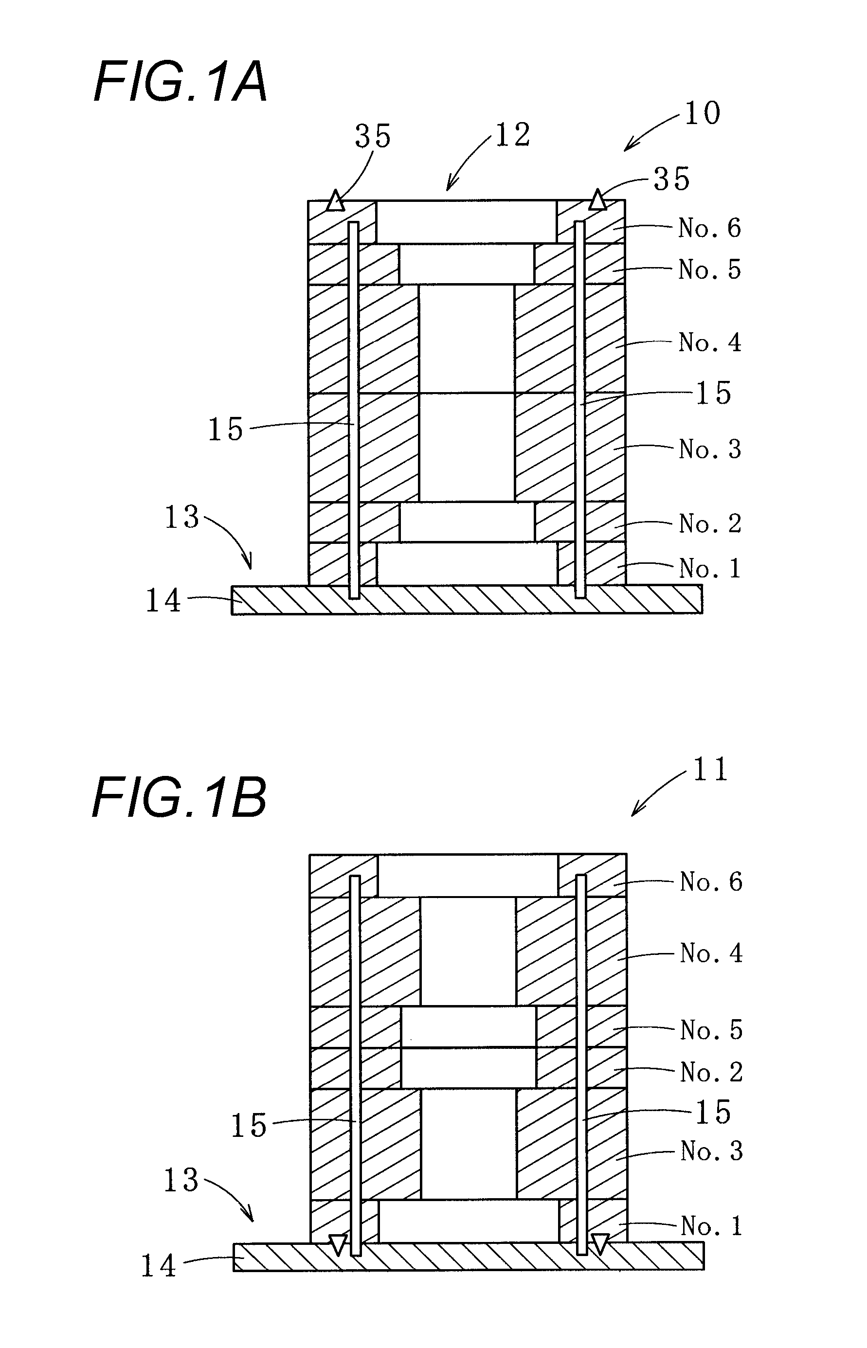
[0045]First, a laminated iron core 10 manufactured using a method for manufacturing the laminated iron core according to one embodiment of the present invention will be described with reference to FIG. 1A.

[0046]The laminated iron core 10 is a rotor iron core (or simply called as a rotor).

[0047]This laminated iron core 10 is formed by sequentially rotating and laminating plural (six herein) block iron cores No. 1 to No. 6 formed by respectively laminating plural annular iron core pieces. Here, the block iron cores No. 1 and No. 6, No. 2 and No. 5, and No. 3 and No. 4 have the same shape, respectively, but, for example, all the block iron cores may have the same shape or different shapes.

[0048]Also, a laminated iron core 11 of FIG. 1B can be formed by reversing the front and back of each of the block iron cores No. 1 to No. 6 s...


PUM

PropertyMeasurementUnit
Thicknessaaaaaaaaaa
Shapeaaaaaaaaaa

Abstract

There is provided a method for manufacturing a laminated iron core. The method includes receiving a plurality of block iron cores which are temporarily laminated and ejected from a die, each block iron core being formed by laminating a plurality of iron core pieces that are blanked from a thin plate workpiece using the die, individually separating the temporarily laminated block iron cores by a block iron core separating unit, and rotating and laminating each of the separated block iron cores by a rotating and laminating unit in order different from order of lamination of the temporarily laminated block iron cores before separation in a place different from a location of the die.

Description

CROSS REFERENCE TO RELATED APPLICATION[0001]This application is based upon and claims the benefit of priority of Japanese Patent Application No. 2015-138881 filed on Jul. 10, 2015, the contents of which are incorporated herein by reference in its entirety.BACKGROUND OF THE INVENTION[0002]1. Field of the invention[0003]The present invention relates to a method for manufacturing a laminated iron core by rotating and laminating a plurality of block iron cores respectively formed by laminating a plurality of iron core pieces blanked from a thin plate workpiece using a die, in a place (that is, the outside of the die) different from a location of the die, and an apparatus for manufacturing the laminated iron core.[0004]2. Description of the Related Art[0005]A laminated iron core is formed by laminating plural iron core pieces blanked from a thin plate workpiece. Since this thin plate workpiece has a plate thickness deviation, each of the iron core pieces is rotated by a given angle and t...

Claims


Application Information

Patent Timeline
IPC IPC(8): H02K15/02B23K37/047
CPCB23K37/047H02K15/02H02K15/03B23K37/0435B23K37/0461B23K31/02B23K2101/06B23K2103/04
Inventor SASAKI, HIDEMISHIBUTA, TADASHI
Owner MITSUI HIGH TEC INC
Why Eureka
Try Eureka