Cutting device and cutting method

Active Publication Date: 2016-09-29
TOWA
View PDF2 Cites 5 Cited by
  • Summary
  • Abstract
  • Description
  • Claims
  • Application Information

AI Technical Summary

Benefits of technology

This patent aims to provide a cutting device and method that can correct the position of an object to be cut, even if there is a displacement in the external electrodes. The device uses a conveyance mechanism and cutting jig with marks to accurately cut the object along a cutting line without damaging the marks. The technical effect is to prevent defective products from occurring.

Problems solved by technology

Furthermore, the cutting jig is shaved, thereby shortening the life of the cutting jig.
According to cutting device 10 disclosed in Japanese Patent Laying-Open No. 2009-170501, however, the following problems arise.
If the BGA substrate is cut in the state where the position of the solder ball is displaced from the dividing line, a part of the solder ball may be damaged.
When the solder ball is damaged, the quality of a singularized BGA product is deteriorated, so that a defective product may be produced.

Method used


Image

  • Cutting device and cutting method
  • Cutting device and cutting method
  • Cutting device and cutting method

Examples


first embodiment

[Modification of First Embodiment]

[0074]As a modification of the first embodiment, the displacement amount of solder ball 5 can be corrected in the following manner.

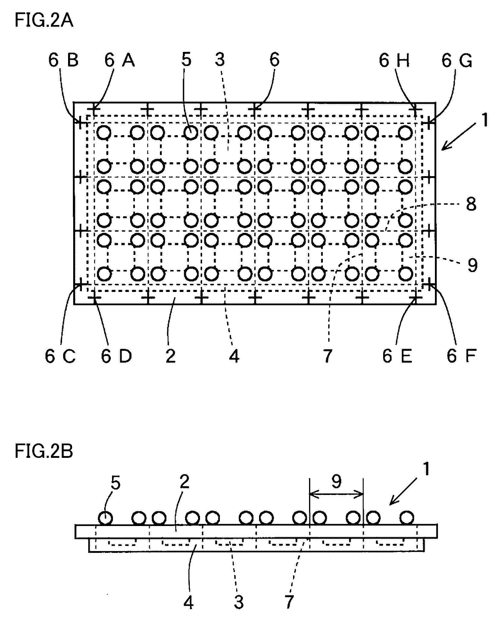
[0075]As the first modification, the coordinate position of first mark 19 provided in cutting jig 11, the coordinate position of second mark 6 in BGA substrate 1 placed on cutting jig 11, and the coordinate position of solder ball 5 are measured. Controller 100 performs data processing of each of the measured coordinate positions, thereby calculating a relative displacement amount between solder ball 5 and each cutting groove. The displacement amount of solder ball 5 is corrected, to set a cutting line on a line connecting intermediate points each located between solder balls 5 formed in regions 9 adjacent to each other. Thus, BGA substrate 1 can be cut.

[0076]In this case, the coordinate position of first mark 19 provided in cutting jig 11, the coordinate position of second mark 6 in BGA substrate 1 placed on cutting jig...

second embodiment

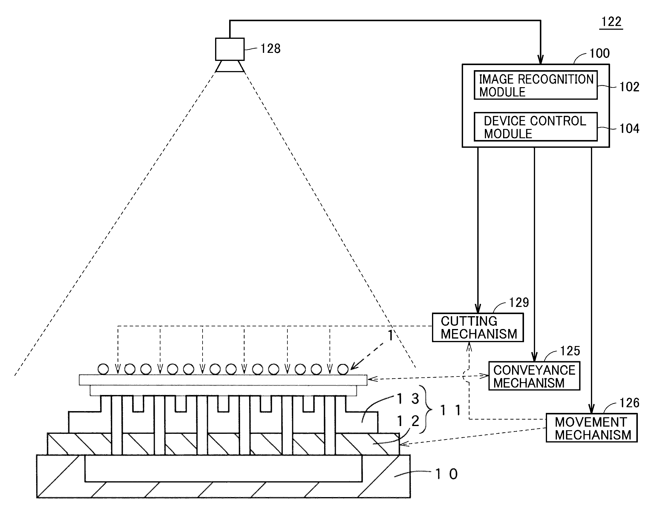
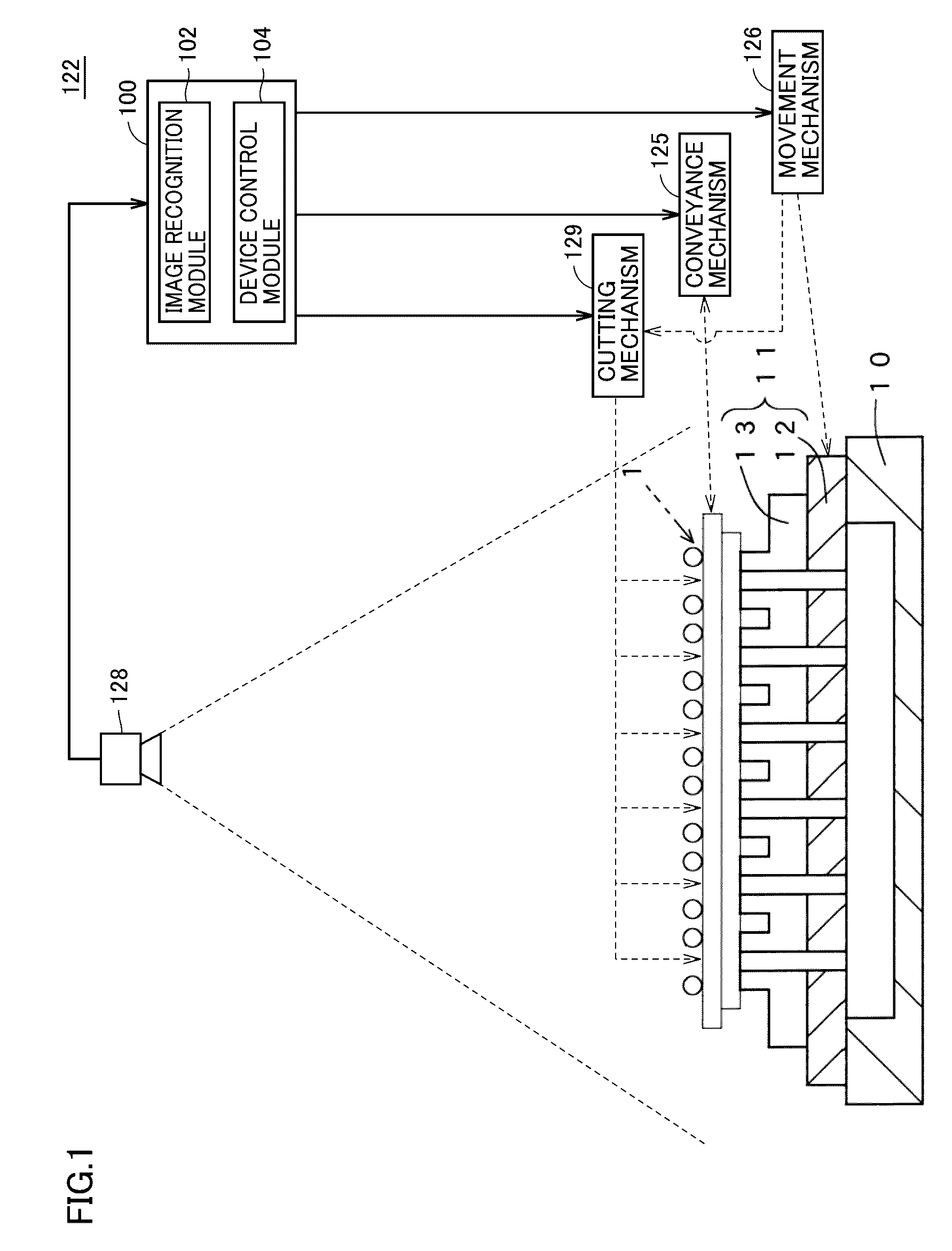
[0078]The cutting device according to the second embodiment of the present invention will be hereinafter described with reference to FIG. 7. As shown in FIG. 7, cutting device 22 serves to singularize an object to be cut into a plurality of products. Cutting device 22 includes a substrate feeding module A, a substrate cutting module B, and a checking module C as components. These components (each of modules A to C) are attachable to / detachable from and exchangeable with each other.

[0079]Substrate feeding module A is equipped with: a substrate feeding mechanism 23 feeding BGA substrate 1 corresponding to an object to be cut; a substrate placement unit 24 delivering BGA substrate 1; and a conveyance mechanism 25 conveying BGA substrate 1. BGA substrate 1 is fed in the state where the side of substrate 2 having solder ball 5 (see FIGS. 2A and 2B) formed thereon faces up. Conveyance mechanism 25 is movable in the X direction, the Y direction and the Z direction, and rotatable in the di...


PUM


Abstract

A cutting device includes: an imaging module for capturing first marks and third marks, to produce primary image data; and a control module for aligning, by a conveyance mechanism, a cutting jig and an object to be cut that is placed on the cutting jig. The control module compares first positional information including positional information of a specific first mark stored or first positional information with third positional information to calculate a primary displacement amount showing a relative positional displacement between a plurality of cutting grooves and the plurality of third marks, respectively. The conveyance mechanism picks up the object from the cutting jig, and the conveyance mechanism and the cutting jig are moved relative to each other based on the primary displacement amount, to move the object by the primary displacement amount to a primary target position. The cutting mechanism cuts the object along a plurality of cutting lines.

Description

BACKGROUND OF THE INVENTION[0001]1. Field of the Invention[0002]The present invention relates to a cutting device and a cutting method for cutting an object to be cut to manufacture a plurality of singularized products.[0003]2. Description of the Background Art[0004]A substrate made of a printed circuit board, a lead frame or the like is imaginarily partitioned into a plurality of lattice-shaped regions. Then, after one chip-shaped element or a plurality of chip-shaped elements (for example, a semiconductor chip) is / are mounted on each of the regions, the entire substrate is resin-sealed. The resulting product obtained in this way is referred to as a “sealed substrate”. The sealed substrate is cut by a cutting mechanism employing a rotary blade or the like and singularized into region units, each of which is provided as a product.[0005]Conventionally, a cutting device has been used to cut a prescribed region of the sealed substrate by a cutting mechanism such as a rotary blade. Firs...

Claims


Application Information

Patent Timeline
IPC IPC(8): H01L21/66H01L21/67H01L21/78H01L21/68B26D5/00B26D7/01
CPCH01L22/20B26D5/007H01L21/67092H01L21/78H01L21/681B26D7/01B28D5/0005B28D5/0058H01L21/304B26D7/0006H01L22/12H01L2924/181H01L23/544H01L24/97H01L2223/5442H01L2223/54426H01L2223/54486H01L2924/15311H01L21/4853H01L2924/00012
Inventor SHIRAI, KATSUMASAMOCHIZUKI, HIROTOISHIBASHI, KANJI
Owner TOWA
Why Eureka
Try Eureka