

Linkage rod including limited-displacement flexible mechanism
- Summary
- Abstract
- Description
- Claims
- Application Information
AI Technical Summary
Benefits of technology
Problems solved by technology
Method used
Image

Examples
first exemplary embodiment
3. First Exemplary Embodiment
3.1) Structure
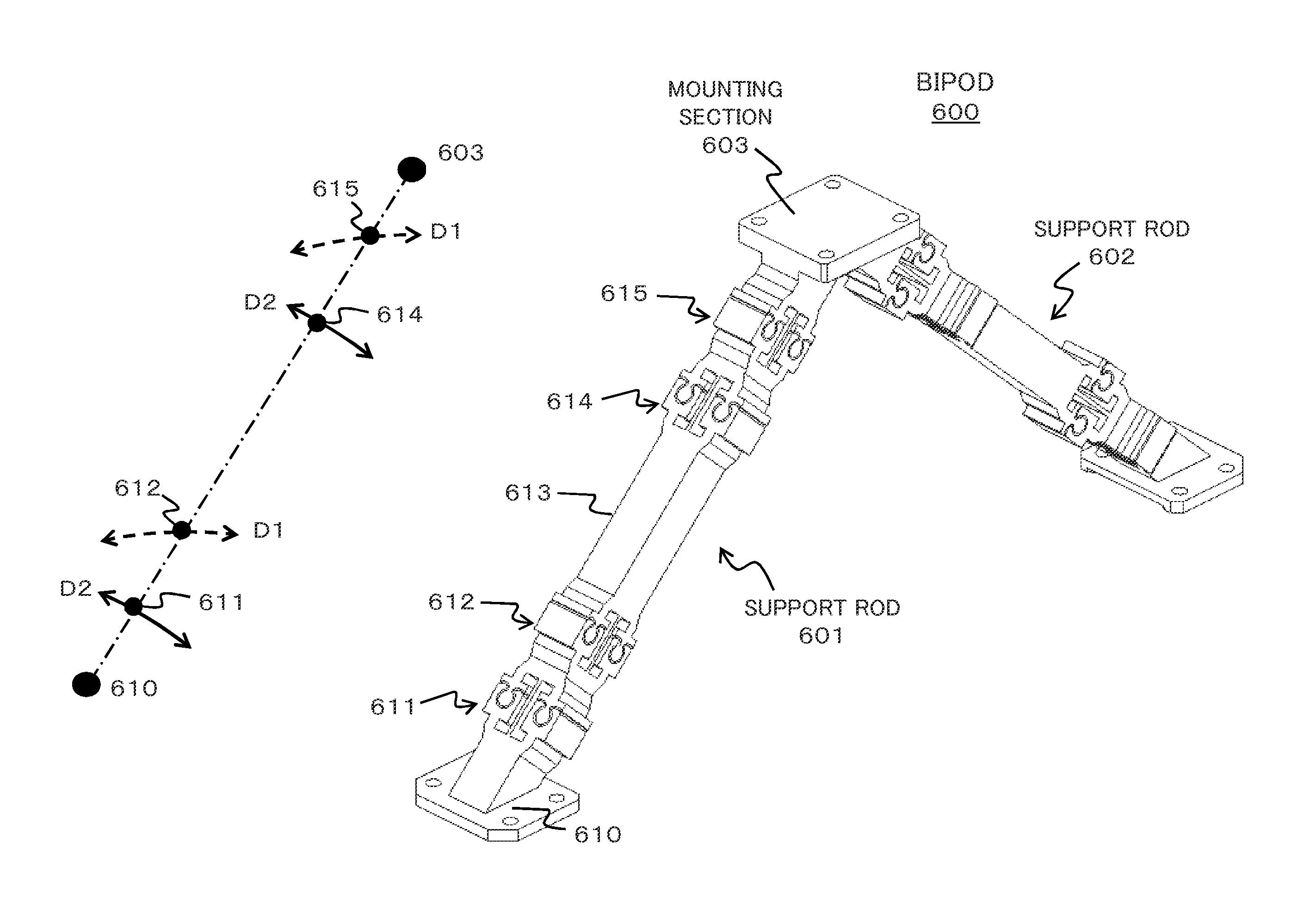
[0058]Referring to FIG. 8, a support assembly using a bipod composed of two linkage rods according to a first exemplary embodiment of the present invention is composed of a bipod 600 and the linear motion mechanism 20 as described above. The bipod 600 has two support rods 601 and 602, one ends of which are connected at a top provided with a support section 603 to form an upside-down V-shaped bipod. The other ends of the support rods 601 and 602 are fixed to the movable section 305 of the first linear motion section 300 and the movable section 405 of the second linear motion section 400, respectively. The support rods 601 and 602 have the same structure. Hereinafter, the structure of the support rod 601 shown in FIGS. 9-11 will be described as an example.
3.2) Bipod
[0059]Referring to FIGS. 9-11, the support rod 601 is shaped like a leg including a fixed portion 610, two limited-displacement flexible joints 611 and 612, a relatively rigid rod ...
second exemplary embodiment
4. Second Exemplary Embodiment
4.1) Structure
[0069]Referring to FIGS. 17-21, a hexapod arrangement having six degrees of freedom includes a base plate 701, a top plate 702 and three support assemblies A, B and C, each of which is composed of the bipod (600A, 600B, 600C) and the linear motion mechanism (20A, 20B and 20C) as shown in FIG. 8. The support assemblies A, B and C are fixed and arranged on the base plate 701 with regular-triangular configuration as typically shown in FIG. 20. The top plate 702 is fixed to the support sections of the bipods 600A, 600B and 600C. Accordingly, the top plate 702 is supported by three position-adjustable points.
[0070]As an example, the base plate 701 is circular and the top plate 702 is star-shaped. The top plate 702 may be formed of three legs 702A, 702B and 702C joined at a center point with the angle between any two adjacent legs being 120 degrees. The three legs 702A, 702B and 702C are supported respectively by the support assemblies A, B and ...
PUM
 Abstract
Description
Claims
Application Information