Insulated Concrete Ledge Form Reinforcement Member

a technology of reinforcement member and ledge, which is applied in the direction of structural elements, building components, building reinforcements, etc., can solve the problems of large structure that is difficult to store, transport and place, and achieve the effect of convenient connection, convenient placement into a form, and simple construction

Active Publication Date: 2017-05-11
NAUJOKS RICHARD
View PDF25 Cites 5 Cited by
  • Summary
  • Abstract
  • Description
  • Claims
  • Application Information

AI Technical Summary

Benefits of technology

[0023]By providing a ledge reinforcement member which includes a hook on only one end with a suitable seat portion on the opposing end which mates directly with the rebar chair of a respective one of the form ties, the reinforcement member can be readily placed into a form without bending or alignment being required. The member is first hooked onto the rebar in the longitudinal slot of the sloped outer form wall followed by simply dropping the seat portion into mating connection with the respective rebar chair of the form tie. The seat portion permits a quick self alignment of the reinforcement member relative to the form tie which in turn automatically aligns the hook and bridge portion of the reinforcement member in the longitudinal direction relative to respective corbel cavities. When providing two hook members spaced apart on opposite sides of a single seat portion, the reinforcement member can be readily hooked into place and centrally aligned within two adjacent corbel cavities with a single placement and alignment of the seat portion relative to one of the form ties. Furthermore, the reinforcement member is relatively small and simple in construction so as to minimize cost and difficulty associated with manufacturing, transport and storage prior to installation in a concrete ledge form.

Problems solved by technology

The large structure is awkward to store, transport and place in the forms due to the preassembled configuration thereof.
Placement of the hook shaped rebar requires time consuming individual placement, alignment, and typically some bending to effectively hook the rebar onto both longitudinally extending rebar members in the rebar chairs of the sloped form wall and the form ties.

Method used


Image

  • Insulated Concrete Ledge Form Reinforcement Member
  • Insulated Concrete Ledge Form Reinforcement Member
  • Insulated Concrete Ledge Form Reinforcement Member

Examples


Embodiment Construction

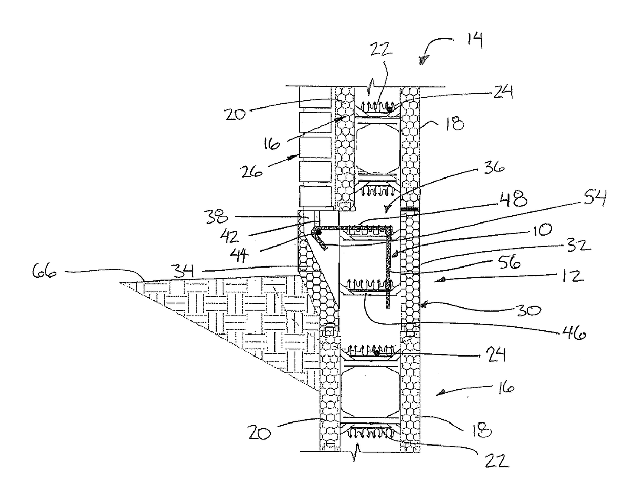
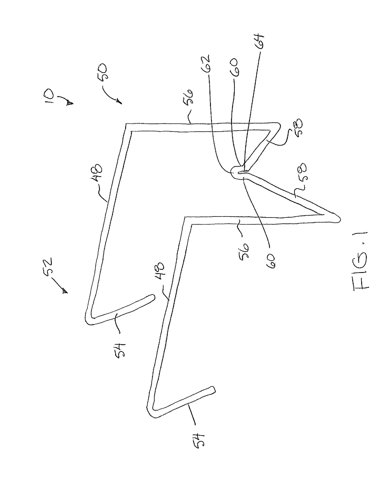
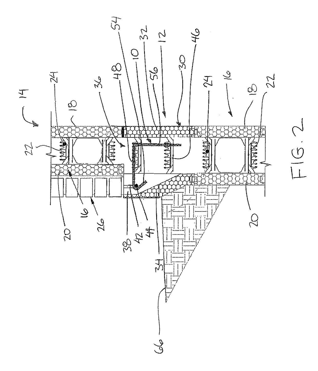
[0048]Referring to the accompanying figures, there is illustrated an insulated concrete ledge form reinforcement member generally indicated by reference numeral 10. The reinforcement member 10 is suited for use in reinforcing a concrete brick ledge formed using an insulated concrete ledge form. The ledge form 12 typically comprises one component of an overall insulated concrete form wall construction 14.

[0049]The insulated concrete forms typically comprise blocks 16 abutted in an end to end configuration in rows which are stacked one upon the other to form a vertical wall. Each of the blocks is typically formed with a suitable interlocking connection for alignment and joining to adjacent blocks formed in the wall. More particularly, each block 16 has an inner insulated wall portion 18 and an outer insulated wall portion 20 which are supported parallel and spaced apart by rigid webs 22, also known as form ties, to define a main concrete receiving cavity therebetween. The webs 22 whic...


PUM


Abstract

A reinforcement member is used with an insulated concrete ledge form including a straight inner form wall, a sloped outer form wall defining a longitudinal slot for receiving an elongate rebar member parallel to the inner form wall, and a plurality of form ties connected between the inner and outer form walls across a main concrete receiving cavity, in which each form tie defines at least one rebar chair for connection to a rebar member. The reinforcement member has i) a bridge portion to extend laterlly from an inner end to an outer end, ii) a hook portion depending from the outer end of the bridge portion so as to extend over and hook onto the elongate rebar member; and iii) a seat portion depending from the inner end of the bridge portion for mating connection with a respective rebar chair of a respective one of the form ties.

Description

[0001]This application claims the benefit under 35 U.S.C. 119(e) of U.S. provisional application Ser. No. 62 / 251,995, filed Nov. 6, 2015.FIELD OF THE INVENTION[0002]The present invention relates to a reinforcement member for use in an insulated concrete ledge form comprising a straight form wall and a sloped form wall joined by form ties, and more particularly the present invention relates to a reinforcement member which is arranged to be connected between rebar chairs in the form ties and a rebar member in a rebar chair of the sloped form wall.BACKGROUND[0003]A known wall construction method comprises the use of insulated concrete forms into which concrete is poured and set. Typical insulated concrete forms comprise blocks which are abutted end to end in rows stacked on upon the other to form a vertical wall. Each block typically comprises an inner insulated wall portion and an outer insulated wall portion which are supported parallel and spaced apart from one another by webs conne...

Claims


Application Information

Patent Timeline
Patent Type & Authority Applications(United States)
IPC IPC(8): E04C5/16
CPCE04C5/163E04C5/16E04B2005/322
Inventor NAUJOKS, RICHARD
Owner NAUJOKS RICHARD
Why Eureka
Try Eureka