View Locking Multi-Monitor Screen Magnifier

a multi-monitor, magnifier technology, applied in the field of screen magnification software, to achieve the effect of smooth movemen

Active Publication Date: 2017-05-11
FREEDOM SCI
View PDF1 Cites 0 Cited by
  • Summary
  • Abstract
  • Description
  • Claims
  • Application Information

AI Technical Summary

Benefits of technology

[0009]A view locking feature locks the mouse to the current viewing area in single monitor while keeping the mouse in view, allowing it to be moved freely within the limits of a stationary background. Furthermore, this feature provides additional functionality for moving smoothly between monitors in a multi-monitor setting by allowing the user to move the mouse from an application on one monitor to an application on the other monitor while circumventing the undesired behavior of shifting the view in either monitor. The magnified views will stay stationary and the mouse will go directly from one application view to the other when a keystroke combination is pressed in conjunction with mouse movement.
[0011]In another example, the low vision user opens up a bank statement report on a web browser and moves to the upper right of the report initially to read the account totals. The user typically spends about five (5) seconds at this screen position or view before panning to other areas of the report (as it is magnified by the screen magnification software). The view predictor function in this case stores the Cartesian coordinates of the view where the user moves to and then idles for a preset period of time (i.e., five seconds). Thus, the view predictor function in this example subsequently sets a view automatically even though the lower vision user was only reading screen contents and not interacting with an interface control object. An advantage of the view predictor function is that the screen view upon magnification is not arbitrarily set for the low vision user. Rather, the view is set dynamically based upon the past interactions of the low vision user so the user can immediately start interacting with the magnified interface without having to pan to an area of initial interest repeatedly.

Problems solved by technology

However, the user also may need to be able to freely move the mouse between the monitors while keeping the viewing area static in each monitor.

Method used


Image

  • View Locking Multi-Monitor Screen Magnifier
  • View Locking Multi-Monitor Screen Magnifier
  • View Locking Multi-Monitor Screen Magnifier

Examples


Embodiment Construction

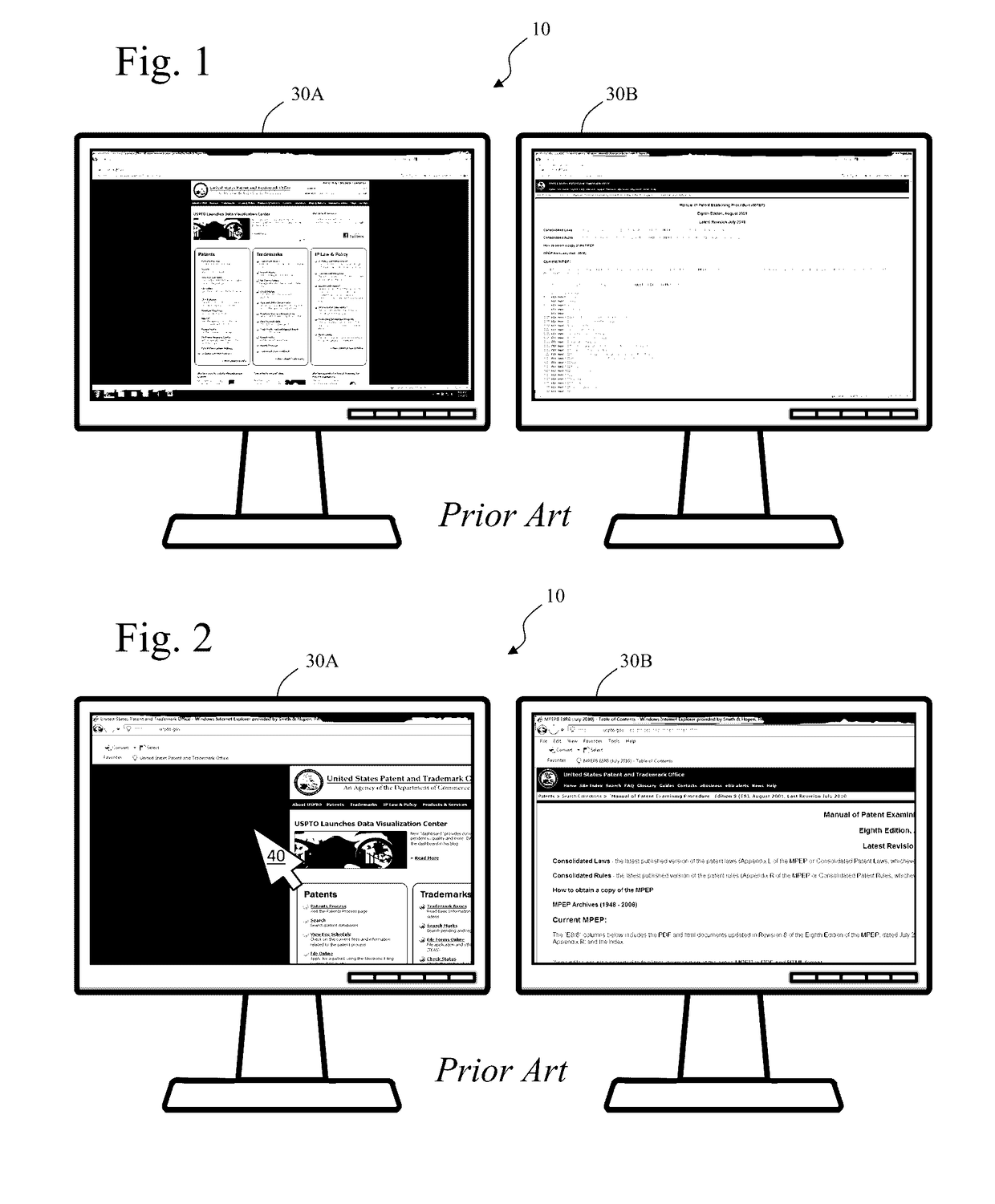
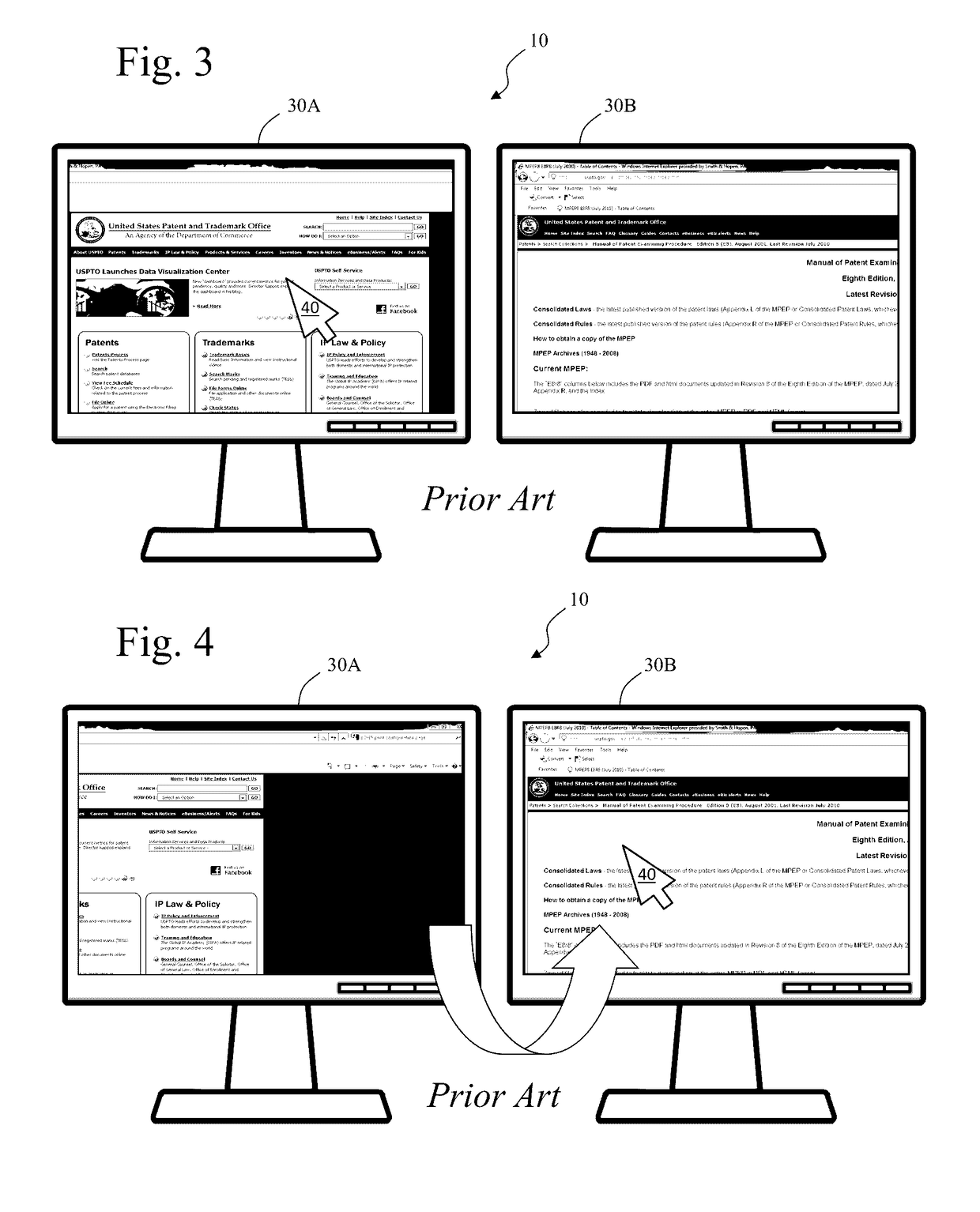
[0033]Turning to FIG. 1, dual monitor system 10 is represented having left monitor 30A and right monitor 30B displaying an extended desktop with two separate web browser windows. In FIG. 2, screen magnification software zooms each monitor to 2× magnification. Mouse 40 is shown over a 2× magnified view in left monitor 30A. In FIG. 3, end user moves mouse 40 towards the center of a web browser in left monitor 30A and for the purposes of this discussion, this first view is what end user wants to maintain.

[0034]In FIG. 4, end user wishes to move mouse 40 to right monitor 30B. However, in doing so, end user loses first view in left monitor 30A as the movement of the mouse scrolls the zoomed-in desktop canvas in left monitor 30A away from first view towards the right side of the screen. When mouse 40 arrives at the left edge of left monitor 30B it will always be at the left side of the desktop canvas of right monitor 30B. In FIG. 5, end user moves mouse 40 downward to second view in right...


PUM


Abstract

A method of locking magnified screen views including the steps of magnifying a portion of a graphic user interface on a first monitor to establish a first magnified view having upper, lower, left and right boundaries, magnifying a portion of the graphic user interface on a second monitor to establish a second magnified view having upper, lower, left and right boundaries, whereby the graphic user interface of the first monitor is extended in the direction of the second monitor, responsive to an end-user selectable setting, restricting pointer indicia movement to an area defined by the boundaries of each view that are not between first and second monitor, and responsive to pointer indicia moving from first monitor towards second monitor displaying pointer indicia within second magnified view responsive to pointer indicia crossing the boundary of first magnified view in the direction of second monitor.

Description

CROSS-REFERENCE TO RELATED APPLICATIONS[0001]This non-provisional application is a divisional of U.S. Non-Provisional patent application Ser. No. 13 / 952,383 entitled “View Locking Multi-Monitor Screen Magnifier” filed on Jul. 26, 2013, which is a national entry of PCT / US2012 / 020044 filed on Jan. 3, 2012, which claims priority to the U.S. provisional patent application No. 61 / 429,303, filed on Jan. 3, 2011.BACKGROUND[0002]1. Field of the Invention[0003]This invention relates to screen magnification software and, more specifically, to a feature to lock a magnified view.[0004]2. Background of the Invention[0005]Screen magnification software generally comprises a software application loaded on a personal computer by optical disc or by download from the Internet. The software runs at a low level, frequently intercepting internal messaging at the operating system level and even to graphic display drivers. Magnification software, to be effective, must be available across the entire operati...

Claims


Application Information

Patent Timeline
Patent Type & Authority Applications(United States)
IPC IPC(8): G06F3/0484G06F3/0481
CPCG06F3/04845G06F2203/04805G06F3/04847G06F2203/04806G06F3/1431G09G2340/045G06F3/0481
Inventor VOORHEES, GARALD LEEGORDON, GLENDAMERY, ERICSIMKOVITZ, DANIEL
Owner FREEDOM SCI
Why Eureka
Try Eureka