Unlock instant, AI-driven research and patent intelligence for your innovation.

Three-dimensional shaping method and three-dimensional shaping device method

a three-dimensional shaping and shape technology, applied in the direction of additive manufacturing processes, manufacturing tools, manufacturing driving means, etc., can solve the problems of high cost of devices and shaped objects, inconvenient colorization of fdm methods, and limited colorization of heads

Inactive Publication Date: 2017-05-18
RICOH KK
View PDF0 Cites 7 Cited by
  • Summary
  • Abstract
  • Description
  • Claims
  • Application Information

AI Technical Summary

Benefits of technology

The invention is a new method and device for 3D shaping that creates solid objects using multiple shaping materials. The technical effect is the ability to create more complex and detailed objects using different materials in a single process.

Problems solved by technology

As the methods suitable for colorization, there are inkjet methods and inkjet binder methods; however, there is a problem in that, as special inkjet heads and ink are necessary, devices and shaped objects are expensive.
However, it is generally said that the FDM method is not suitable for colorization as compared to the inkjet methods or the inkjet binder methods.
However, there is a problem in that the number of colors is limited to the number of heads.
However, Japanese Unexamined Patent Application Publication No. 2013-86289 does not consider colorization of shaped objects, and does not mention a specific method of mixing shaping raw materials.

Method used


Image

  • Three-dimensional shaping method and three-dimensional shaping device method
  • Three-dimensional shaping method and three-dimensional shaping device method
  • Three-dimensional shaping method and three-dimensional shaping device method

Examples


first embodiment

l Shaping Method and Theory Thereof

[0058]An explanation is given of the three-dimensional shaping method according to an embodiment of the present invention. FIG. 2 is a schematic view of the shaping material to be formed, where in the case of FIG. 2A, there are 2 types of shaping raw materials, and in the case of FIG. 2B, there are 3 types of shaping raw materials. Furthermore, in the following equations, the subscript index a represents the parameter with regard to a shaping raw material A, the subscript index b represents the parameter with regard to a shaping raw material B, and the subscript index x represents the parameter with regard to the formed shaping material.

[0059]First, an explanation is given of a case where there are 2 types of shaping raw materials.

[0060]If the operational relationship in FIG. 2A is represented using general equations, the following Equation (1) and Equation (2) are obtained.

Qx=Qa+Qb=¼π(da2×va+db2×vb)=¼π×dx2×vx  (1)

fx=VxPx(2)

[0061]Here, the conveyin...

second embodiment

Shaping Device

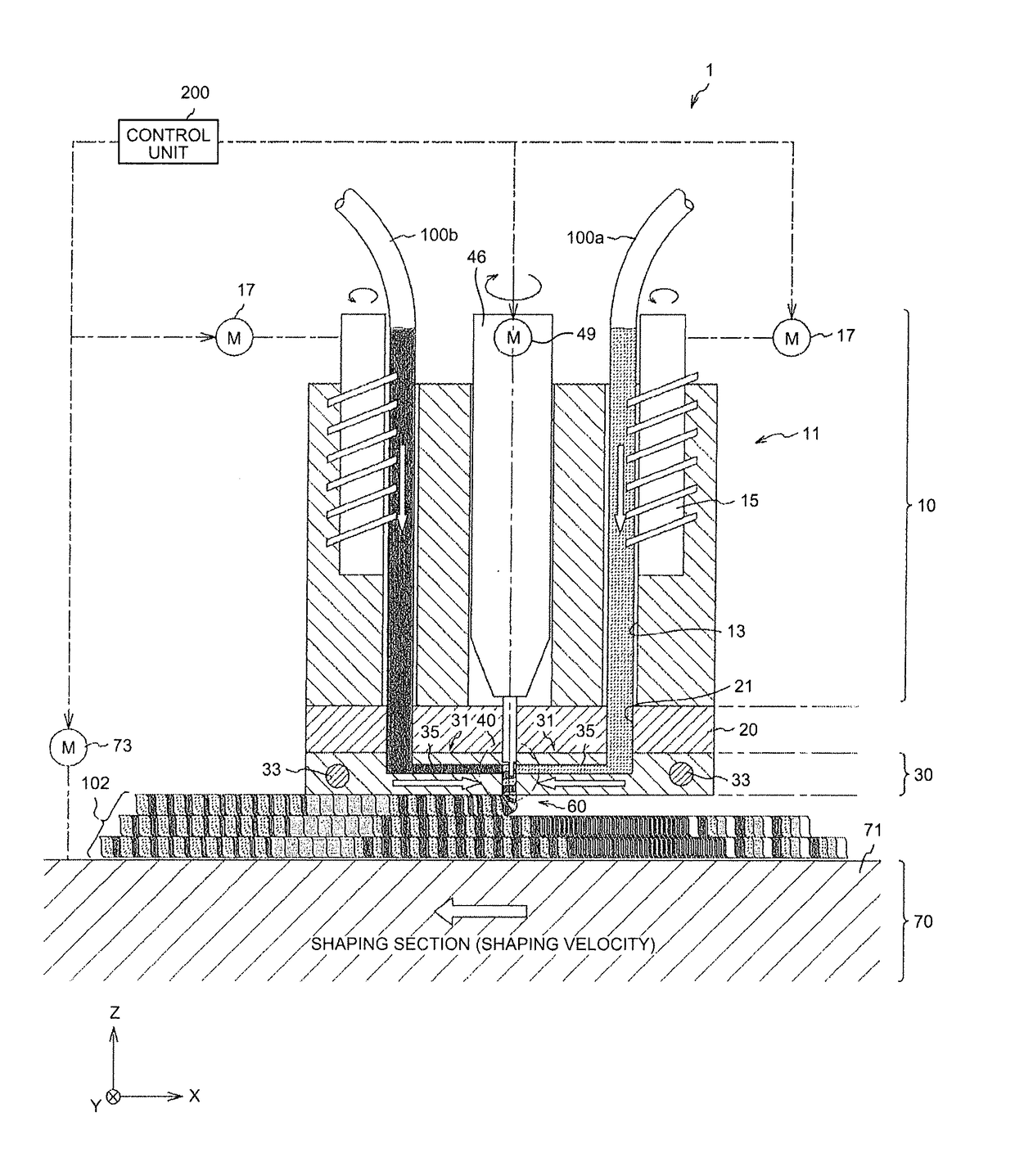
[0117]With reference to FIGS. 7 to 9, an explanation is given of a three-dimensional shaping device that implements the three-dimensional shaping method. FIG. 7 is a cross-sectional view that schematically illustrates the three-dimensional shaping device according to a second embodiment of the present invention. FIG. 8 is an enlarged cross-sectional view that schematically illustrates the relevant part of a shaping-material forming section. FIG. 9 is a perspective view that schematically illustrates the relevant part of the shaping-material forming section.

[0118]A three-dimensional shaping device 1 is a device that forms a three-dimensional shaped object using a fused deposition modeling (FDM) method, in which a shaping raw material 100 is melted (deformed) and deposited in a predetermined solid shape.

[0119]The schematic operations of the three-dimensional shaping device 1 are as follows. The three-dimensional shaping device 1 melts the shaping raw material 100 at a he...

third embodiment

l Shaping Device

[0175]An explanation is given of a three-dimensional shaping device according to a third embodiment of the present invention. FIGS. 11A to 11B are views that schematically illustrate the relevant part of the shaping-material forming section of the three-dimensional shaping device according to the third embodiment of the present invention, FIG. 11A is a longitudinal sectional view, and FIG. 11B is a C-C cross-sectional view of FIG. 11A. Hereafter, the same reference numerals are applied to the same members as in the first embodiment, and the explanations of the same members are omitted.

[0176]In the three-dimensional shaping device according to the present embodiment, the twisting section 40 includes a cylindrical rotary member 83 that includes multiple flow paths (conveyance paths) 85 that each convey the deformed shaping raw material 100 in each color; and multiple discharge openings 65 that are provided at one end (the lower end in the drawing) in the axial directio...


PUM

PropertyMeasurementUnit
Thicknessaaaaaaaaaa
Speedaaaaaaaaaa
Shapeaaaaaaaaaa

Abstract

A three-dimensional shaping method deforms and deposits a plurality of shaping raw materials in a predetermined solid shape. The three-dimensional shaping method includes: by a conveying unit, conveying the plurality of shaping raw materials to a deforming unit; by the deforming unit, deforming the shaping raw materials; by a shaping-material forming unit, twisting and arranging the deformed shaping raw materials in a helical fashion to form a shaping material; and by a shaping unit, sequentially depositing the shaping material to form a three-dimensional shaped object.

Description

CROSS-REFERENCE TO RELATED APPLICATIONS[0001]This application is a continuation of PCT international application Ser. No. PCT / JP2015 / 062346 filed on Apr. 23, 2015 which designates the United States, and which claims the benefit of priority from Japanese Patent Application No. 2014-131439, filed on Jun. 26, 2014; the entire contents of which are incorporated herein by reference.BACKGROUND OF THE INVENTION[0002]1. Field of the Invention[0003]The present invention relates to three-dimensional shaping methods for deforming and depositing a shaping raw material to obtain a three-dimensional shaped object and, more particularly, to a three-dimensional shaping method for generating a shaped object using multiple shaping raw materials and a three-dimensional shaping device that is suitable for the method.[0004]2. Description of the Related Art[0005]As a technology for forming a three-dimensional solid object, the technology called Rapid Prototyping (RP) is known. This technology uses data (...

Claims


Application Information

Patent Timeline
IPC IPC(8): B29C67/00B33Y30/00B33Y10/00
CPCB29C67/0055B33Y30/00B33Y10/00B29C67/00B29C64/241B29C64/118B29C64/106
Inventor KANEMATSU, TOSHIHIROMATSUBARA, MAYUMI
Owner RICOH KK