Imaging apparatus and imaging method

a technology which is applied in the field of imaging apparatus and imaging method, can solve the problems of difficult to accurately detect translational shake, increase computing load, and complex system, and achieve the effect of correcting image blur and simple structur

Active Publication Date: 2017-08-24
FUJIFILM CORP
View PDF0 Cites 1 Cited by
  • Summary
  • Abstract
  • Description
  • Claims
  • Application Information

AI Technical Summary

Benefits of technology

[0011]According to the invention, it is possible to provide an imaging apparatus and an imaging method that can correct an image blur caused by a rotational shake and a translational shake with a simple structure.

Problems solved by technology

In high magnification imaging at a short object distance, the influence of a translational shake in addition to a rotational shake of an imaging apparatus increases and it is difficult to accurately detect the translational shake using only the angular velocity information of an angular velocity sensor.
However, since the acceleration sensor is provided, there is a concern that the system will become complicated and computing load will increase.

Method used


Image

  • Imaging apparatus and imaging method
  • Imaging apparatus and imaging method
  • Imaging apparatus and imaging method

Examples


Embodiment Construction

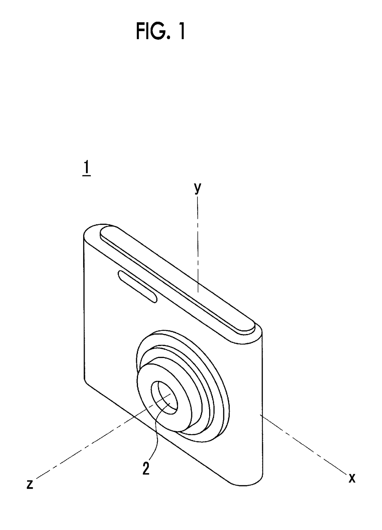
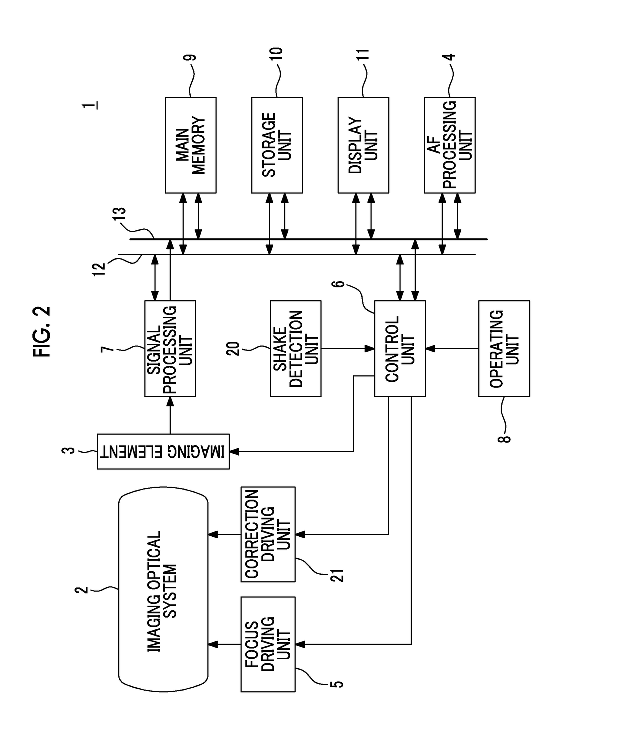
[0037]FIG. 1 illustrates the outward appearance of an example of an imaging apparatus for describing an embodiment of the invention and FIG. 2 illustrates the structure of the imaging apparatus illustrated in FIG. 1.

[0038]A digital camera 1 which is an example of the imaging apparatus illustrated in FIGS. 1 and 2 comprises an imaging optical system 2 including, for example, a focus lens for focusing, an imaging element 3 that captures an image of an object through the imaging optical system 2, an auto focus (AF) processing unit 4 that determines a focus position of the focus lens, a focus driving unit 5 that moves the focus lens to the focus position determined by the AF processing unit 4, and a control unit 6.

[0039]For example, a charge coupled device (CCD) image sensor or a complementary metal oxide semiconductor (CMOS) image sensor is used as the imaging element 3.

[0040]A signal processing unit 7 performs analog signal processing, such as a correlated double sampling process, for...


PUM


Abstract

An imaging apparatus includes: a distance detection unit that detects an object distance; a shake detection unit that detects an amount of shake of the imaging apparatus; a driving unit that moves an optical element or an imaging element included in an imaging optical system to correct an image blur caused by a shake of the imaging apparatus; and a control unit that calculates an amount of movement of the optical element or the imaging element moved by the driving unit based on the amount of shake detected by the shake detection unit and controls the driving unit, and the control unit directs the imaging element to continuously capture images in response to an imaging instruction and changes a correction gain which is used to calculate the amount of movement for each imaging operation, depending on the object distance detected by the distance detection unit.

Description

CROSS REFERENCE TO RELATED APPLICATION[0001]This is a continuation of International Application No. PCT / JP2015 / 082773 filed on Nov. 20, 2015, and claims priority from Japanese Patent Application No. 2014-236589 filed on Nov. 21, 2014, the entire disclosures of which are incorporated herein by reference.BACKGROUND OF THE INVENTION[0002]1. Field of the Invention[0003]The present invention relates to an imaging apparatus and an imaging method.[0004]2. Description of the Related Art[0005]An imaging apparatus having a function of correcting an image blur due to the shake of the imaging apparatus caused by, for example, a hand shake has been known. In the correction of the image blur, for example, the amount of rotational shake of the imaging apparatus is calculated on the basis of angular velocities about a pitch axis and a yaw axis which are perpendicular to an optical axis of an imaging optical system and a correction optical system or an imaging element is moved such that an image blu...

Claims


Application Information

Patent Timeline
Patent Type & Authority Applications(United States)
IPC IPC(8): H04N5/232
CPCH04N5/23287H04N5/23267H04N5/2329H04N5/23258H04N23/6812H04N23/687H04N23/683H04N23/689
Inventor ITO, HISAO
Owner FUJIFILM CORP
Why Eureka
Try Eureka