
Imaging apparatus and control method thereof

a technology of image stabilization and control method, which is applied in the direction of color television details, television system details, television systems, etc., can solve the problems of inability to execute pt image stabilization and pt driving together, drawback which position should be used as a reference for pt image stabilization process, and prior art not described, so as to achieve accurate image blur correction

Active Publication Date: 2019-05-23
CANON KK
View PDF2 Cites 2 Cited by
  • Summary
  • Abstract
  • Description
  • Claims
  • Application Information

AI Technical Summary

Benefits of technology

The present invention is about a technology that accurately corrects image blurring in a camera. It uses a driver to change the camera's position and detects shake to determine which part of the image needs correction. This results in a better quality image that is easier to analyze and interpret.

Problems solved by technology

However, the prior art disclosed in Japanese Patent Application Laid-Open No. 2004-312138 is to avoid an unnecessary image stabilization operation caused by a vibration generated due to the PT driving, and does not describe the following drawbacks relating to image blur correction control using the PT mechanism.
Specifically, there has been a drawback which position should be used as a reference for the PT image stabilization process.
Additionally, the prior art does not describe an end process of the PT image stabilization.
Additionally, the prior art does not describe any PT driving method in a case in which a PT drive command other than the PT image stabilization is received during the execution of PT image stabilization.
Therefore, even if the PT drive command is received during the execution of PT image stabilization, it is not possible to execute the PT image stabilization and PT driving together.

Method used


Image

  • Imaging apparatus and control method thereof
  • Imaging apparatus and control method thereof
  • Imaging apparatus and control method thereof

Examples


first embodiment

Modification of First Embodiment

[0042]In the first embodiment, although a description will be given of an open loop control method that does not use feedback in the PT image stabilization process, the present invention is not limited thereto. In the modified example, after the PT drive target value is calculated in step S505 in FIG. 5, the current positions of the panning drive unit and the tilting drive unit are acquired, the difference between the current position and the PT drive target value is calculated, and feedback control is performed. Therefore, the PT image stabilization control having a higher reliability can be performed.

[0043]Additionally, in the modified example, a speed for returning the PT drive position to the offset position after receiving the PT image stabilization end command is changed in accordance with the amplitude and frequency of the detection signal of the shake detecting unit 104. For example, if the shake frequency is low, the PT drive position is slow...

second embodiment

Modification of Second Embodiment

[0063]In the second embodiment, although an example of performing the determination process whether or not the reception drive remaining amount is equal to or larger than the predetermined value is described in step S605 in FIG. 6, the present invention is not limited thereto. In the modification, a determination process that determines whether or not the drive amount for one cycle calculated in step S602 is equal to or more than a predetermined threshold value is also performed. For example, if the drive amount for one cycle is less than a threshold value, the drive amount for one cycle is not added to the offset position for each process. Instead, once for each predetermined number of processes, a set value in which a value obtained by multiplying the drive amount for one cycle by the predetermined number that is equal to or more than the threshold value is added to the offset position.

[0064]In the modified example, a speed for the driving to the P...


PUM


Abstract

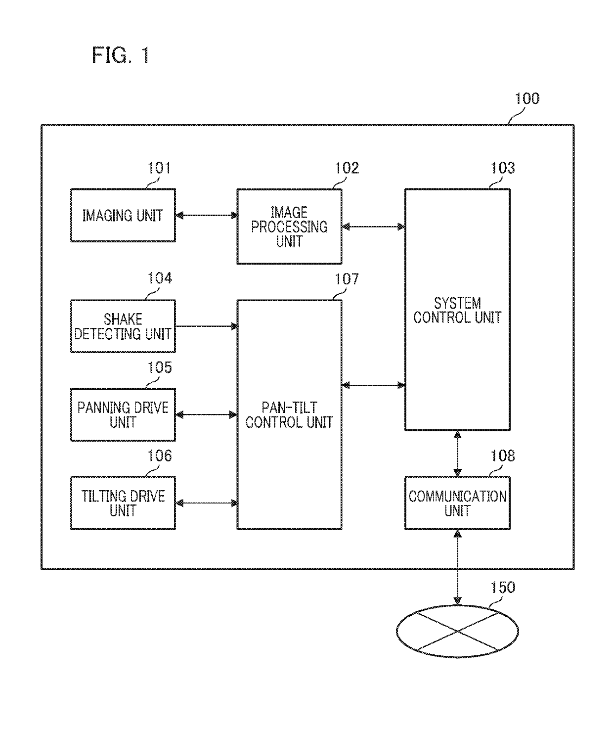
An imaging apparatus includes a panning driver and a tilting driver for changing an imaging direction. A PT (pan-tilt) controller performs image blur correction by using at least one of a panning driver and a tilting driver, based on a shake detection signal of the imaging apparatus. The PT controller stores the position information of the current driver in a memory before each driver is driven in an image blur correcting start process. With the stored position as a reference position, image blur correction is performed by using the shake detection signal. After the end of the image blur correction control, the PT controller sets the position stored in the memory to the drive target value and controls the operation of each driver.

Description

BACKGROUND OF THE INVENTIONField of the Invention[0001]The present invention relates to an imaging apparatus having a driver that changes an imaging direction, and a control method thereof.Description of the Related Art[0002]A pan-tilt (hereinafter, also referred to as “PT”) device in a network camera controls and monitors an imaging direction and a field angle by remote control via a network or a dedicated line. In this type of the imaging apparatus, a panning (horizontal rotation) operation and a tilting (vertical rotation) operation are performed by a camera head. Additionally, in the imaging apparatus having an electric zoom function, a shooting angle can be changed by remote control.[0003]In an imaging apparatus having an image stabilization function (image blur correcting function) for reducing a blur of a captured image caused by a vibration of an installation environment, electronic correction or optical correction is performed. In the electronic correction, image blur corre...

Claims


Application Information

Patent Timeline
Patent Type & Authority Applications(United States)
IPC IPC(8): H04N5/232H04N23/40
CPCH04N5/23264H04N5/23216H04N5/23261H04N5/23229H04N23/6812H04N23/685H04N23/695H04N23/95H04N23/682H04N23/62H04N23/80H04N23/6815
Inventor IDAKA, SAYURI
Owner CANON KK
Learn More