Image stabilizing apparatus, optical apparatus having the same, and image stabilizing method
a technology of image stabilization and optical equipment, which is applied in the direction of color television details, television system details, television systems, etc., can solve the problems of insufficient correction of image blurs and deterioration of image stabilization performance, and achieve the effect of correcting image blurs, reducing offset variation in output signals, and high accuracy
- Summary
- Abstract
- Description
- Claims
- Application Information
AI Technical Summary
Benefits of technology
Problems solved by technology
Method used
Image
Examples
first embodiment
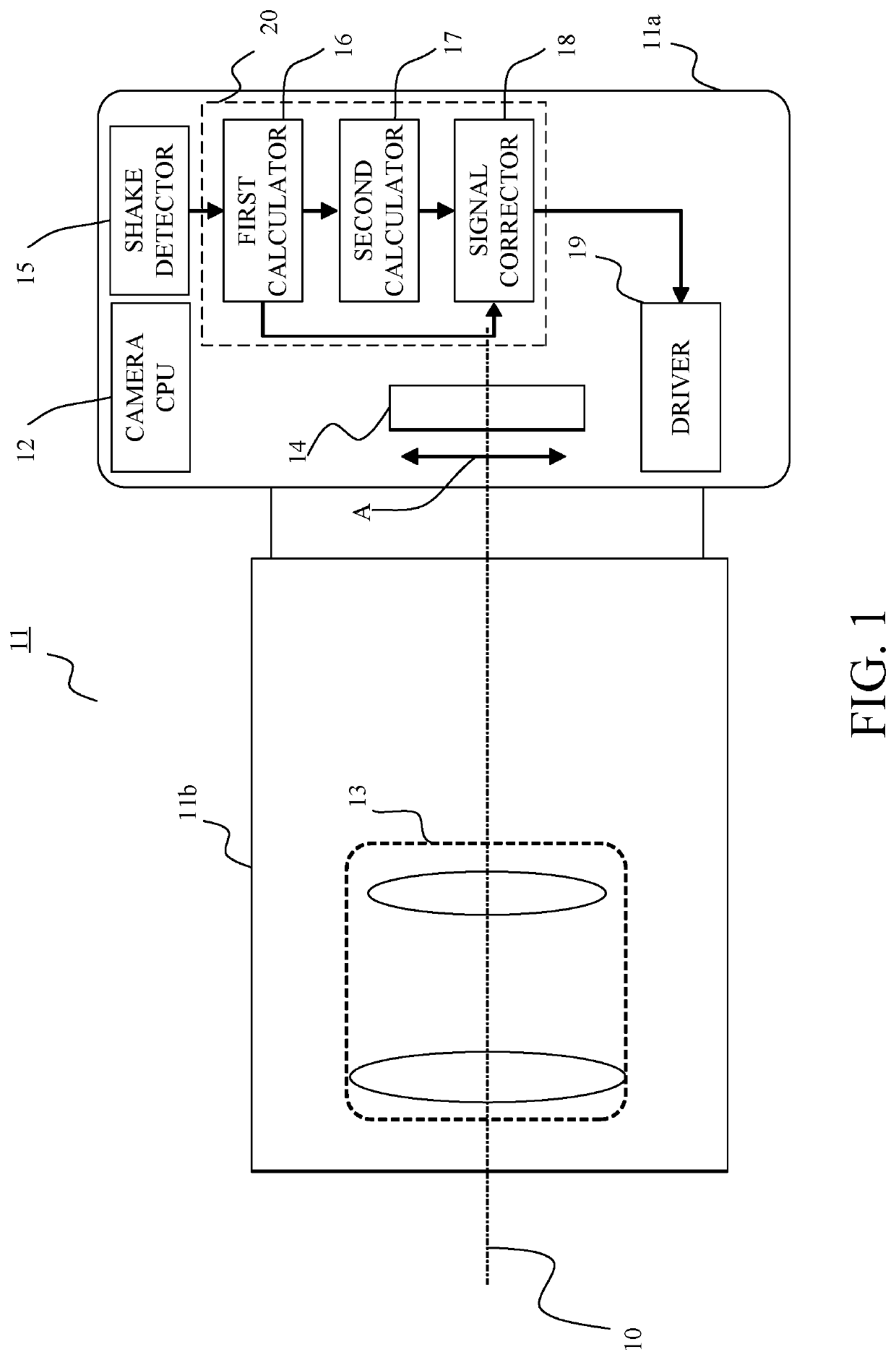
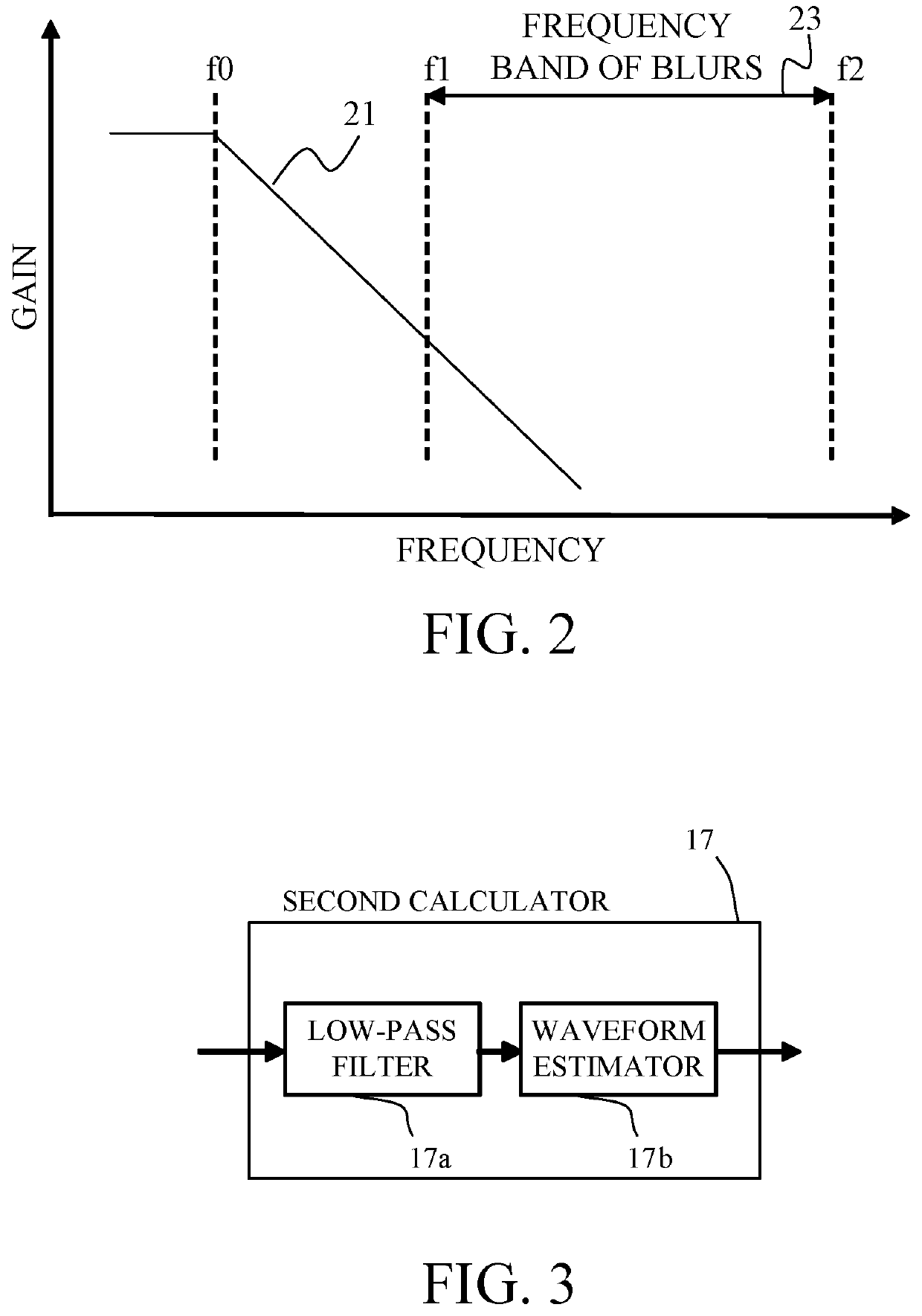
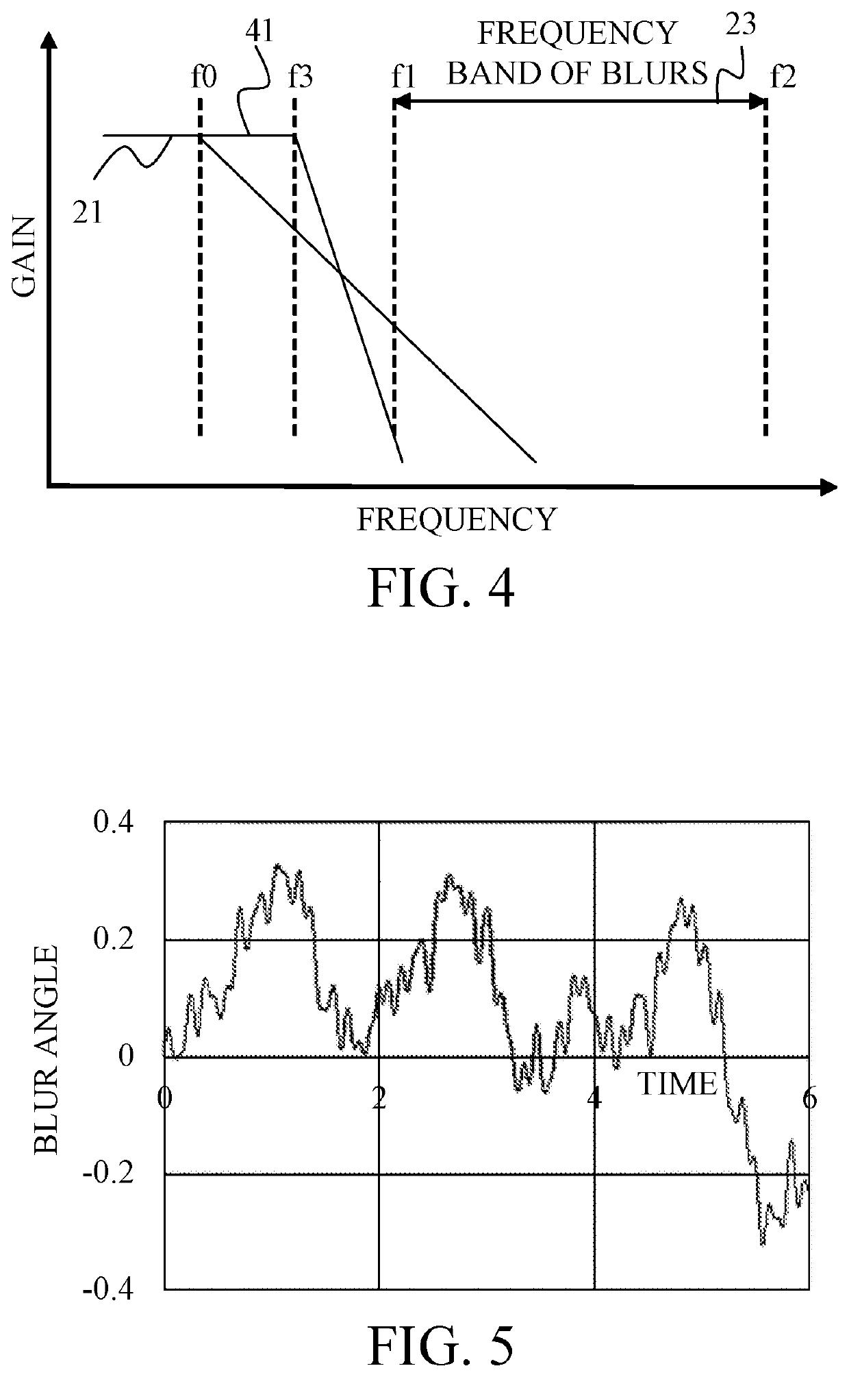
[0032]FIG. 1 is a block diagram of a digital camera 11 which is an example of an optical apparatus according to this embodiment. The digital camera 11 includes a camera body 11a, and an interchangeable lens 11b that can be attached to and detached from the camera body 11a. The camera body 11a includes a camera CPU 12, an image sensor (corrector) 14, a shake detector 15, a first calculator (first calculation task) 16, a second calculator (second calculation task) 17, a signal corrector (correction task) 18, and a driver 19. In this embodiment, the image stabilizing apparatus 20 includes the first calculator 16, the second calculator 17, and the signal corrector 18. The interchangeable lens 11b has an imaging optical system 13. This embodiment describes a digital camera as an example of an optical apparatus equipped with an image stabilizing apparatus, but the present invention is not limited to this embodiment. The image stabilizing apparatus may be mounted on another optical apparat...
second embodiment
[0061]This embodiment reduces the order of the low-pass filter when the elapsed time after the second calculator starts is short and increases the order of the low-pass filter over time, in order to reproduce the time change in the offset variation in the output signal from the shake detector.
[0062]FIG. 9 is a block diagram of a digital camera 91 which is an example of the optical apparatus according to this embodiment. The digital camera 91 includes a camera body 91a, and an interchangeable lens 91b that can be attached to and detached from the camera body 91a. The camera body 91a includes the image sensor 14. The interchangeable lens 91b includes the imaging optical system 13, a lens CPU 92, a shake detector 95, a first calculator (first calculation task) 96, a second calculator (second calculation task) 97, a signal corrector (correction task) 98, and a driver 99. In this embodiment, the image stabilizing apparatus 100 includes the first calculator 96, the second calculator 97, a...
third embodiment
[0083]This embodiment changes, over time after the second calculator starts (increases the time constant), the break frequency of the low-pass filter to the low-frequency side, in order to reproduce the time change of the offset variation in the output signal from the shake detector.
[0084]FIG. 15 is a block diagram of a digital camera 151 which is an example of the optical apparatus according to this embodiment. The digital camera 151 includes a camera body 151a, and an interchangeable lens 151b that can be attached to and detached from the camera body 151a. The camera body 151a includes the image sensor 14, a camera CPU 152, a shake detector 155, a first calculator (first calculation task) 156, a second calculator (second calculation task) 157, a signal corrector (correction task) 158, and a driver 159. The interchangeable lens 151b includes the imaging optical system 13, a lens CPU 252, a shake detector 255, a first calculator (first calculation task) 256, a second calculator (sec...
PUM
 Abstract
Description
Claims
Application Information
 - R&D
- Intellectual Property
- Life Sciences
- Materials
- Tech Scout
- Unparalleled Data Quality
- Higher Quality Content
- 60% Fewer Hallucinations
Browse by: Latest US Patents, China's latest patents, Technical Efficacy Thesaurus, Application Domain, Technology Topic, Popular Technical Reports.
© 2025 PatSnap. All rights reserved.Legal|Privacy policy|Modern Slavery Act Transparency Statement|Sitemap|About US| Contact US: help@patsnap.com


