Image capture apparatus and control method thereof

a technology of image capture and control method, which is applied in the field of image capture apparatus, can solve the problems of increasing the travel distance of the shutter curtain, increasing the amount of power consumed, and darkening of the image periphery, so as to suppress light falling off in the periphery area and correct image blurring

Active Publication Date: 2020-10-01
CANON KK
View PDF0 Cites 0 Cited by
  • Summary
  • Abstract
  • Description
  • Claims
  • Application Information

AI Technical Summary

Benefits of technology

[0005]The present invention has been conceived in light of these problems with conventional techniques. One aspect of the present invention makes it possible, in an image capture apparatus capable of correcting image blurring by moving an image sensor and a method for controlling the image capture apparatus, to suppress light-fall-off in periphery areas of an image while using the image stabilization.

Problems solved by technology

With an image stabilization function that moves the image sensor, there are situations where, when there is an increased amount of movement of the image sensor, light that is supposed to be incident on the periphery of the image sensor is blocked by the shutter frame, causing the periphery areas of the image to become darker, particularly when the diaphragm is at or near the maximum aperture.
Furthermore, the travel distance of the shutter curtain also increases, which increases the amount of power consumed and reduces the upper limit value of the shutter speed.

Method used


Image

  • Image capture apparatus and control method thereof
  • Image capture apparatus and control method thereof
  • Image capture apparatus and control method thereof

Examples


first embodiment

Camera System Configuration

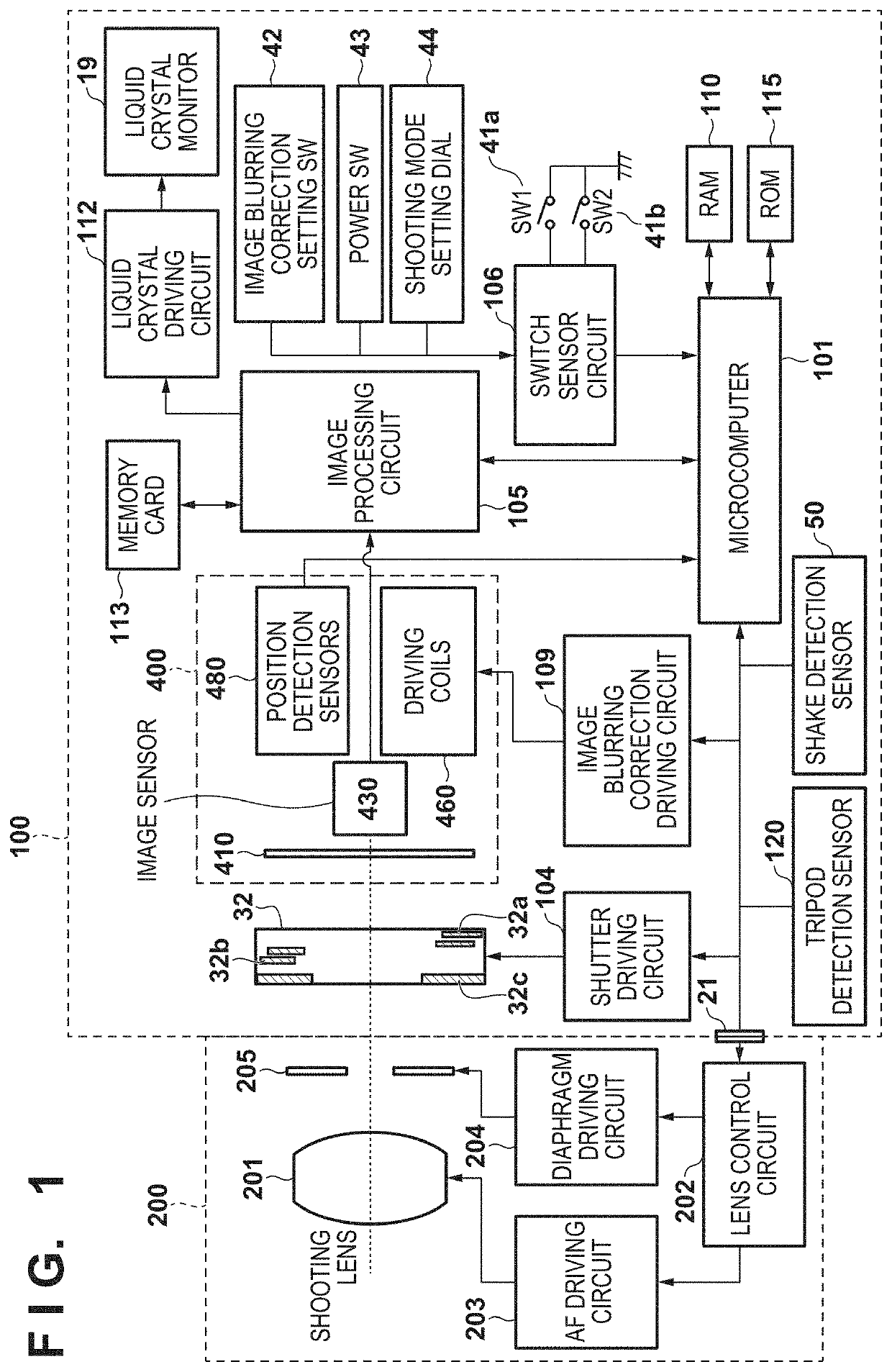
[0017]FIG. 1 is a block diagram schematically illustrating an example of the functional configuration of a camera system according to a first embodiment. The camera system is constituted by a camera body (a digital camera 100) and a lens unit 200 which can be attached to and removed from the camera body.

[0018]A microcomputer (“MPU” hereinafter) 101 functions as a control unit that controls the operations of the various units in the digital camera 100 by loading programs stored in ROM 115 into RAM 110 and executing those programs. Also, by executing programs, the MPU 101 controls the operations of peripheral devices which can communicate with the digital camera 100 (the lens unit 200, a flash device, and so on). Unless otherwise specified, the operations carried out by the MPU 101 in the following descriptions are realized by the MPU 101 executing programs. The MPU 101 may actually be realized by a plurality of microprocessors.

[0019]The MPU 101 communicates...


PUM


Abstract

An image capture apparatus having a correction function that corrects image burring by controlling a position of an image sensor is disclosed. The apparatus controls the correction function in accordance with one of a plurality of modes including a first and second modes. In the first mode, the image sensor can move in a first direction perpendicular to an optical axis of an imaging optical system within a first distance. In the second mode, when an aperture size of a diaphragm in the imaging optical system is greater than or equal to a predetermined value, the image sensor can move in the first direction within a second distance shorter than the first distance.

Description

BACKGROUND OF THE INVENTIONField of the Invention[0001]The present invention relates to an image capture apparatus and a control method thereof, and particularly relates to an image capture apparatus in which the position of an image sensor is variable, and to a control method thereof.Description of the Related Art[0002]Japanese Patent Laid-Open No. 2011-81417 discloses an image capture apparatus that corrects image blurring by controlling the position of an image sensor in accordance with movement of the image capture apparatus.[0003]With an image stabilization function that moves the image sensor, there are situations where, when there is an increased amount of movement of the image sensor, light that is supposed to be incident on the periphery of the image sensor is blocked by the shutter frame, causing the periphery areas of the image to become darker, particularly when the diaphragm is at or near the maximum aperture. Such light-fall-off in the periphery areas is particularly a...

Claims


Application Information

Patent Timeline
Patent Type & Authority Applications(United States)
IPC IPC(8): H04N5/232H04N5/225
CPCH04N5/2251H04N5/23264H04N5/23245H04N23/67H04N23/682H04N23/6812H04N23/73G02B27/646H04N23/667H04N23/687H04N23/54H04N23/55H04N23/70
Inventor URAKAMI, TOSHIFUMI
Owner CANON KK
Why Eureka
Try Eureka