Imaging apparatus and image blur correction method

a technology of image blur and imaging apparatus, which is applied in the direction of printers, cameras, instruments, etc., can solve the problem of displaced focus lens, and achieve the effect of accurate correction of image blur, simple structure and improved accuracy of calculating object distan

Active Publication Date: 2017-08-24
FUJIFILM CORP
View PDF0 Cites 2 Cited by
  • Summary
  • Abstract
  • Description
  • Claims
  • Application Information

AI Technical Summary

Benefits of technology

[0016]According to the invention, it is possible to provide an imaging apparatus and an image blur correction method that can improve the accuracy of calculating an object distance with a simple structure and can accurately correct an image blur.

Problems solved by technology

However, in a case in which force is applied to the focus lens in the optical axis direction by the influence of, for example, gravity, the focus lens is displaced.

Method used


Image

  • Imaging apparatus and image blur correction method
  • Imaging apparatus and image blur correction method
  • Imaging apparatus and image blur correction method

Examples


Embodiment Construction

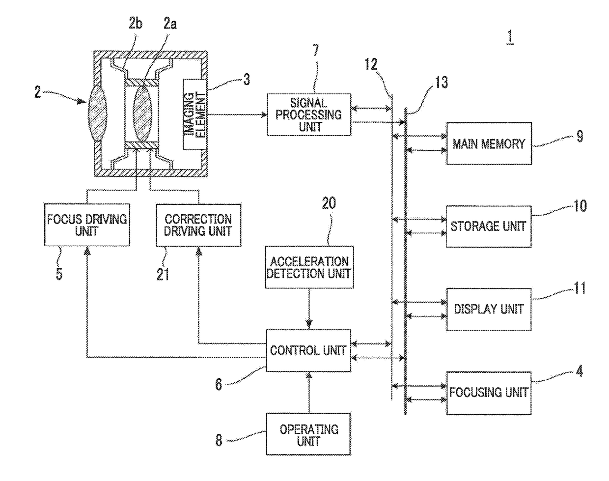
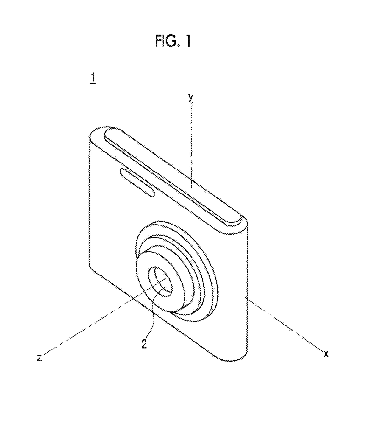
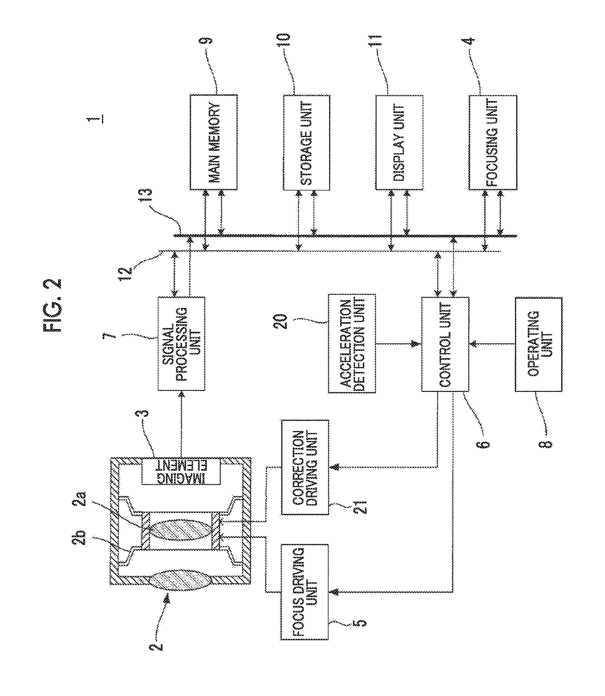
[0026]FIG. 1 illustrates the outward appearance of an example of an imaging apparatus for describing an embodiment of the invention and FIG. 2 illustrates the structure of the imaging apparatus illustrated in FIG. 1.

[0027]A digital camera 1 which is an example of the imaging apparatus illustrated in FIGS. 1 and 2 comprises an imaging optical system 2 including, for example, a movable lens 2a as a focus lens that is supported so as to be movable in an optical axis direction (z-axis direction) and the directions (an x-axis direction and a y-axis direction) of two axes perpendicular to the optical axis direction, an imaging element 3 that captures an image of an object through the imaging optical system 2, a focusing unit 4 that determines a focus position of the movable lens 2a, a focus driving unit 5 that moves the movable lens 2a in the z-axis direction, and a control unit 6.

[0028]The movable lens 2a is elastically supported by a holder spring 2b so as to be movable in the direction...


PUM


Abstract

An imaging apparatus includes: a driving unit that moves a focus lens; a focusing unit that determines a focus state and outputs a focusing signal indicating a focus position of the focus lens; a control unit that controls the driving unit based on the focusing signal; an acceleration detection unit that detects acceleration in directions of three orthogonal axes; a distance calculation unit that calculates an acceleration component in an optical axis direction based on the acceleration in the directions of the three orthogonal axes detected by the acceleration detection unit and calculates an object distance corresponding to the focus position indicated by the focusing signal based on the acceleration component in the optical axis direction; and a shake correction unit that corrects an image blur caused by a translational shake in directions of two orthogonal axes perpendicular to at least an optical axis as defined herein.

Description

CROSS REFERENCE TO RELATED APPLICATION[0001]This is a continuation of international Application No. PCT / JP2015 / 081893 filed on Nov. 12, 2015, and claims priority from Japanese Patent Application No. 2014-244096 filed on Dec. 2, 2014, the entire disclosures of which are incorporated herein by reference.BACKGROUND OF THE INVENTION[0002]1. Field of the Invention[0003]The present invention relates to an imaging apparatus and an image blur correction method.[0004]2. Description of the Related Art[0005]An imaging apparatus has been known which corrects an image blur caused by the shake of the imaging apparatus due to, for example, a hand shake. The shake of the imaging apparatus includes an angular shake of the imaging apparatus about an axis perpendicular to an optical axis and a translational shake of the imaging apparatus in an axial direction perpendicular to the optical axis.[0006]In the correction of an image blur caused by a rotational shake, in general, an angular velocity about t...

Claims


Application Information

Patent Timeline
Patent Type & Authority Applications(United States)
IPC IPC(8): H04N5/232G03B13/36
CPCH04N5/23287H04N5/23258G03B13/36G03B3/10G03B2205/0007G03B2217/005H04N23/67H04N23/6812H04N23/687H04N23/63
Inventor WADA, TETSU
Owner FUJIFILM CORP
Why Eureka
Try Eureka