
Channel accessing method and device in wireless communication system

a wireless communication system and accessing method technology, applied in the direction of electrical equipment, radio transmission, connection management, etc., can solve the problems of increasing the burden of control to measure, increasing the load of the corresponding cell, and time delay in determining the best transmission beam and reception beam, so as to reduce the delay of initial access and perform initial access quickly and efficiently.

Active Publication Date: 2017-09-07
SAMSUNG ELECTRONICS CO LTD
View PDF5 Cites 37 Cited by
  • Summary
  • Abstract
  • Description
  • Claims
  • Application Information

AI Technical Summary

Benefits of technology

[0016]The present invention is capable of reducing initial access time delay between UE and an eNB in a wireless communication system using a beamforming technique, and also interference between ...

Problems solved by technology

In a state where both UE and an eNB employ a beamforming technique, if the UE transmits, to the eNB, an RACH preamble for the initial access, it needs to increase the number of transmission beams and reception beams and thus increases the burden of control to measure and determine a best beam for the beamforming.
In addition, the increase in the number of transmission beams and reception beam...

Method used


Image

  • Channel accessing method and device in wireless communication system
  • Channel accessing method and device in wireless communication system
  • Channel accessing method and device in wireless communication system

Examples


Embodiment Construction

[0032]Various embodiments of the present invention are described in detail with reference to the accompanying drawings. The same reference numbers are used throughout the drawings to refer to the same or similar parts. It should be understood that the accompanying drawings are merely provided to assist in a comprehensive understanding of the invention and are not suggestive of limitation in terms of form, arrangement, etc. Detailed descriptions of well-known functions and structures incorporated herein may be omitted to avoid obscuring the subject matter of the invention. In the description of the invention, certain detailed explanations of related art are omitted when it is deemed that they may unnecessarily obscure the essence of the invention.

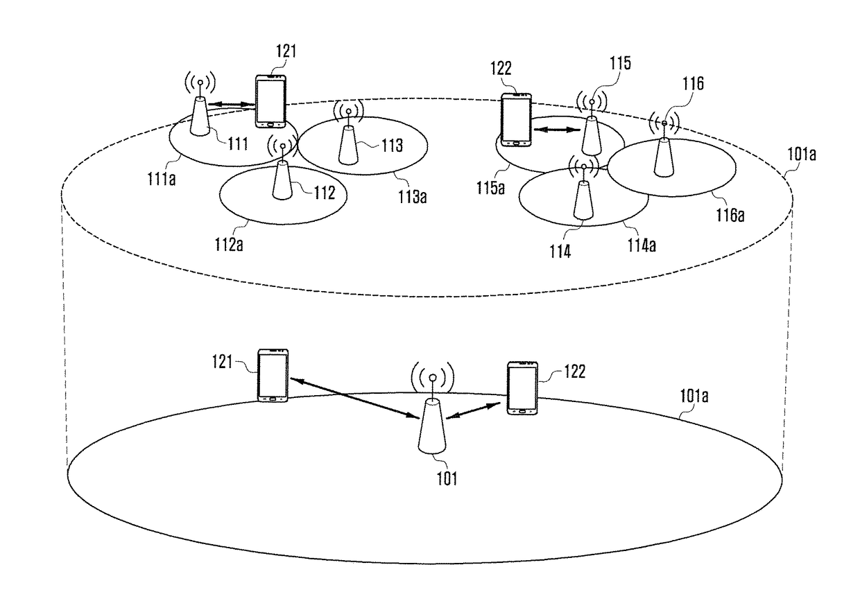
[0033]FIG. 1 is a conceptual diagram that describes a system model where a macro-cell and small cell are capable of connecting to UE, simultaneously, overlappingly.

[0034]With reference to FIG. 1, the system model includes one macro-cell eNB ...


PUM


Abstract

The present invention relates to a channel accessing method and device in a wireless communication system and, particularly, to a channel accessing method and device for a call handover for a terminal in a wireless communication system using a plurality of beams. The method according to an embodiment of the present invention, as a method of controlling a macro cell base station when a terminal that is communicating with the macro cell base station performs channel access with a small cell base station in a wireless network capable of using a plurality of transmitting/receiving beams, may include the steps of: determining whether to request a channel setting for a call for the terminal to the small cell base station when a signal strength measurement report for a channel synchronized with the small cell base station is received from the terminal; providing information including at least one of recommending information on the transmitting/receiving beams of the terminal and position information on the terminal in a request message to the small cell base station when a channel setting request to the small cell base station is decided upon; stopping the transmission of data to the terminal and a set data radio bearer (DRB2) when a response message for accepting the channel setting for the terminal is received from the small cell base station; transmitting a radio resource control access reconfiguration message to the terminal to communicate with the small cell base station; and providing information on data to be transmitted and received by the terminal to the small cell base station.

Description

TECHNICAL FIELD[0001]The present invention relates to a channel access method and apparatus in a wireless communication system, and more particularly, to a channel access method and apparatus in a wireless communication system using a number of beams when handing over a call of UE.BACKGROUND ART[0002]Wireless communication technology has been researched and developed to increase the amount of transmission data and the data transmission rate via user equipment (UE) or eNBs. In order to perform communication between UE and an eNB, they need to be synchronized with each other and thus can transmit / receive data to / from each other. In this case, a link or channel for communication from UE to an eNB is called “uplink,” and a link or channel for communication from an eNB to UE is called “downlink.”[0003]In order to obtain synchronization between UE and an eNB in a wireless communication system, UE is capable of obtaining time synchronization via a Synchronization CHannel (SCH) as a downlin...

Claims


Application Information

Patent Timeline
IPC IPC(8): H04W16/28H04W36/00H04W72/04H04W74/08H04W76/04H04W76/02
CPCH04W16/28H04W76/04H04W36/0016H04W72/046H04W74/0833H04W76/02H04W76/27H04W24/10H04W88/08H04B7/0617H04W36/0072H04W36/04H04B7/0695H04B7/088H04W16/32H04W36/28H04W36/0069H04W92/20
Inventor RYOO, SUNHEUIJUNG, JUNGSOOMOON, JUNGMINNIGAM, ANSHUMANLEE, SUNGJIN
Owner SAMSUNG ELECTRONICS CO LTD
Learn More