
Head-mounted equipment capable of displaying images

Inactive Publication Date: 2017-12-07
TSAI CHENG HO
View PDF0 Cites 2 Cited by
  • Summary
  • Abstract
  • Description
  • Claims
  • Application Information

AI Technical Summary

Benefits of technology

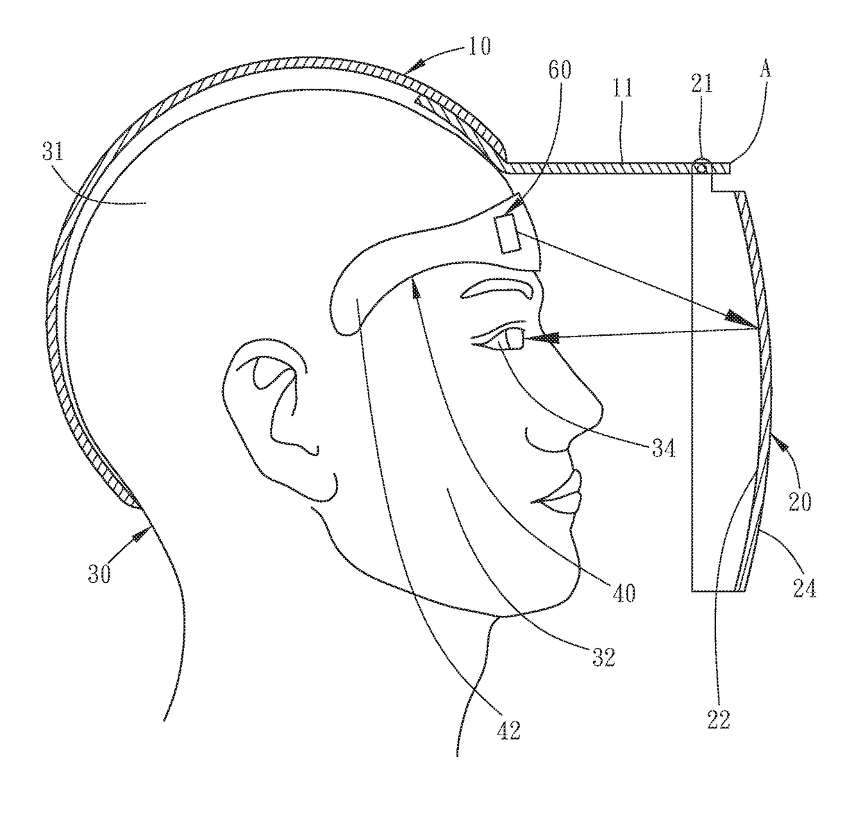
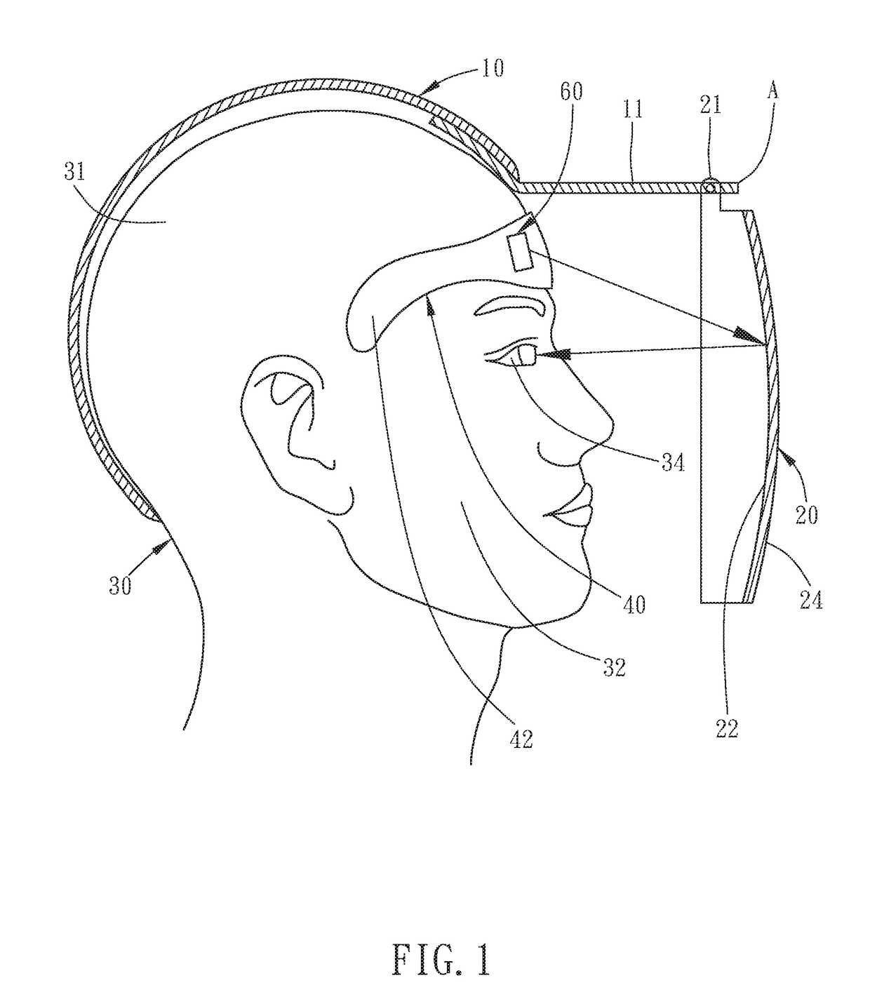
The head-mounted equipment of the invention has a display attached to the face-worn member, which is worn on the user's face to allow for easier viewing of the images. The at least one bracket is also mounted on the visor, which prevents interference with the user's head and ensures clear vision. Overall, this design improves the user's experience and allows for better viewing of the information.

Problems solved by technology

The imaging module is attached to the lower surface of the peak and will protrude from the lower surface of the peak, and as a result, when the cap is worn on the head, the imaging module is likely to hit or interfere with the user's head, or block the user's vision.

Method used


Image

  • Head-mounted equipment capable of displaying images
  • Head-mounted equipment capable of displaying images
  • Head-mounted equipment capable of displaying images

Examples


fourth embodiment

[0056]Referring then to FIG. 12, a head-mounted equipment capable of displaying images in accordance with the present invention is similar to the first preferred embodiment, except that:

[0057]Two ear-hook members 71 are provided at two sides of the face-worn member 40. In this embodiment, the two ear-hook members 71 are two legs 71, each of the two legs 71 has one end connected to two sides of the face-worn member 40, and has another end formed with a hook portion 711 to be hooked to the ears of the user 30. Therefore, without having to be sticky or without having to abut against the face 32 of the user 30, the wearing surface 41 of the face-worn member 40 can also be attached or fixed to the face 32 of the user 30,

[0058]The rest structures of the fourth preferred embodiment are the same as the first preferred embodiment, and therefore, no further description seems necessary.

fifth embodiment

[0059]Referring then to FIG. 13, a head-mounted equipment capable of displaying images in accordance with the present invention is similar to the first preferred embodiment, except that:

[0060]the two ear-hook members 72 are two rope rings 72 which are connected to two sides of the face-worn member 40 and to be hooked to the ears of the user 30. Therefore, the wearing surface 41 of the face-worn member 40 can also be attached or fixed to the face 32 of the user 30, without having to be sticky.

[0061]The rest structures of the fifth preferred embodiment are the same as the first preferred embodiment, and therefore, no further description seems necessary.

sixth embodiment

[0062]Referring then to FIGS. 14-16, a head-mounted equipment capable of displaying images in accordance with the present invention is similar to the first preferred embodiment, except that:

[0063]The face-worn member 40 includes an abutting layer 46 and a substrate 48. The abutting layer 46 is made of silicone rubber with a sticky property. The substrate 48 is provided for mounting of the displays 60 (as shown in FIG. 1). In this embodiment, the outer surface of the abutting layer 46 is provided with the wearing surface 41, and the outer surface of the substrate 48 is provided with the mounting surface 42.

[0064]When in use, the abutting layer 46 of the face-worn member 40 is abutted against the face 32 of the user 30, and the abutting layer 46 is able to be firmly attached to the face 32 of the user 30. In this embodiment, the abutting layer 46 of the face-worn member 40 is made of (but not limited to) silicone rubber, as long as the abutting layer 46 has sticky property and can be ...


PUM


Abstract

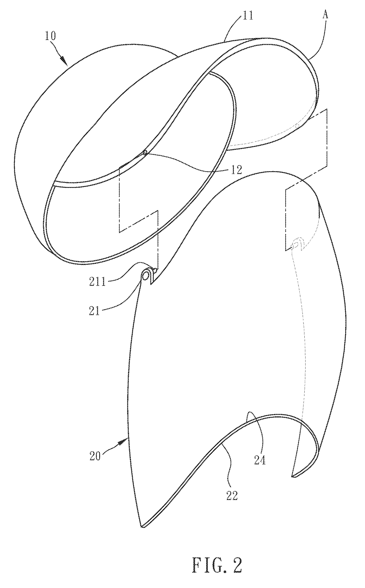
A head-mounted equipment capable of displaying images includes: a head-worn member, a visor, a face-worn member and a display. The head-worn member has a front edge, and the visor is attached to the front edge of the head-worn member and is partially reflective and partially transparent. The face-worn member has a wearing surface and an opposite mounting surface, and the display is mounted on the mounting surface of the face-worn member to project an image to the visor.

Description

BACKGROUND OF THE INVENTIONField of the Invention[0001]The present invention relates to a head-mounted equipment, and more particularly to a head-mounted equipment capable of displaying images.Related Prior Art[0002]A conventional cap-type HUD (head up display) includes: a cap, a reflector and an imaging module. The cap has a peak, and the reflector is pivotally disposed at the front edge of the peak. The reflector is partially reflective and partially transparent. The imaging module is removably attached to the lower surface of the peak, by way of magnetic attraction, adhesive or clipping, to project an image to the reflector, and via the reflector, the image is reflected to a user's eyes.[0003]The imaging module is attached to the lower surface of the peak and will protrude from the lower surface of the peak, and as a result, when the cap is worn on the head, the imaging module is likely to hit or interfere with the user's head, or block the user's vision. Therefore, the above cap...

Claims


Application Information

Patent Timeline
IPC IPC(8): G02B27/01
CPCG02B27/0172G02B27/0176G02B27/0149G02B2027/0169G02B2027/0196G02B2027/013G02B2027/015G02B27/017
Inventor TSAI, CHENG-HO
Owner TSAI CHENG HO
Learn More