
Exercise Machine with Electromagnetic Resistance Selection

a technology of electromagnetic resistance and exercise machine, applied in gymnastic exercise, resilient force resistors, weights, etc., can solve the problems of exercise machine failure, excessive process disruption to exercise routine, and simply inability to exercis

Active Publication Date: 2018-01-18
LAGREE TECH INC
View PDF2 Cites 57 Cited by
  • Summary
  • Abstract
  • Description
  • Claims
  • Application Information

AI Technical Summary

Benefits of technology

The present invention provides an exercise teaching method that allows a class training instructor to change the resistance settings for each exercise on one or more machines by changing the state of electromagnets that engage or disengage biasing members. This allows for greater flexibility and customization in the training process.

Problems solved by technology

However, this process is exceedingly disruptive to an exercise routine.
In practice, this is simply not possible using the currently available exercise machines that require the attaching or detaching multiple resistance-inducing springs from a movable exercise carriage.
Many newer exercisers unfamiliar with these types of machines will need one-on-one assistance from the class training instructor, further disrupting the class and delaying the resumption of the exercise routine.
Class disruption is economically costly to a commercial fitness training enterprise in two key ways: first, experienced exercisers quickly become discouraged at the disruption and delays in the routine, and oftentimes do not return, resulting in direct revenue loss; and secondly, an exercise class that could be performed in thirty minutes will take forty-five minutes or more to complete when accounting for the interruptions, thereby reducing the number of individual class sessions that can be sold to exercisers during business hours.
Longer class times result in a revenue opportunity loss.
Furthermore, the exerciser's tempo is disrupted by the interruptions in a manner that may affect the usefulness of the exercise program.

Method used


Image

  • Exercise Machine with Electromagnetic Resistance Selection
  • Exercise Machine with Electromagnetic Resistance Selection
  • Exercise Machine with Electromagnetic Resistance Selection

Examples


Embodiment Construction

A. Overview.

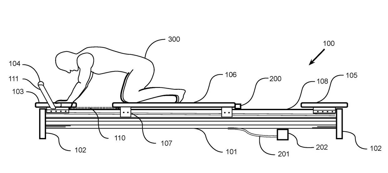
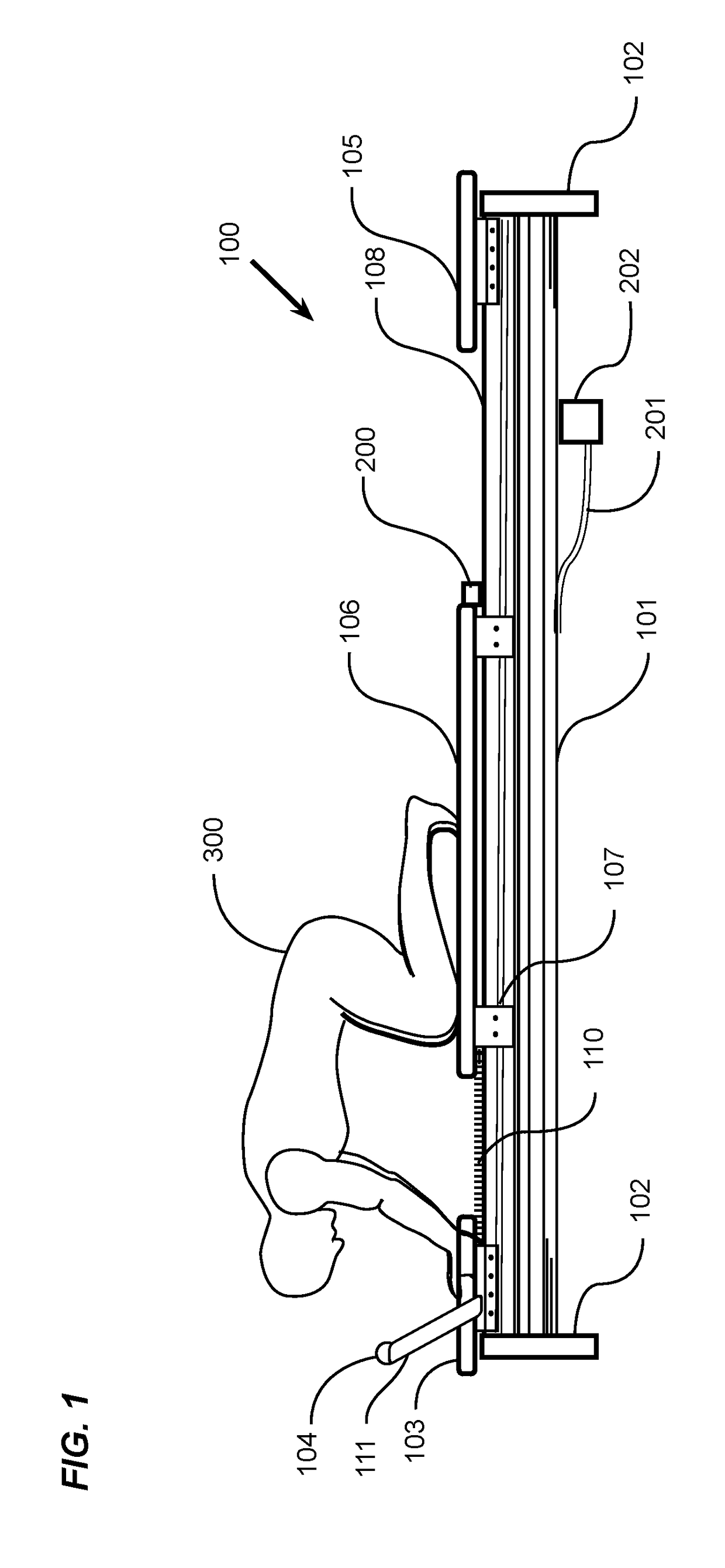
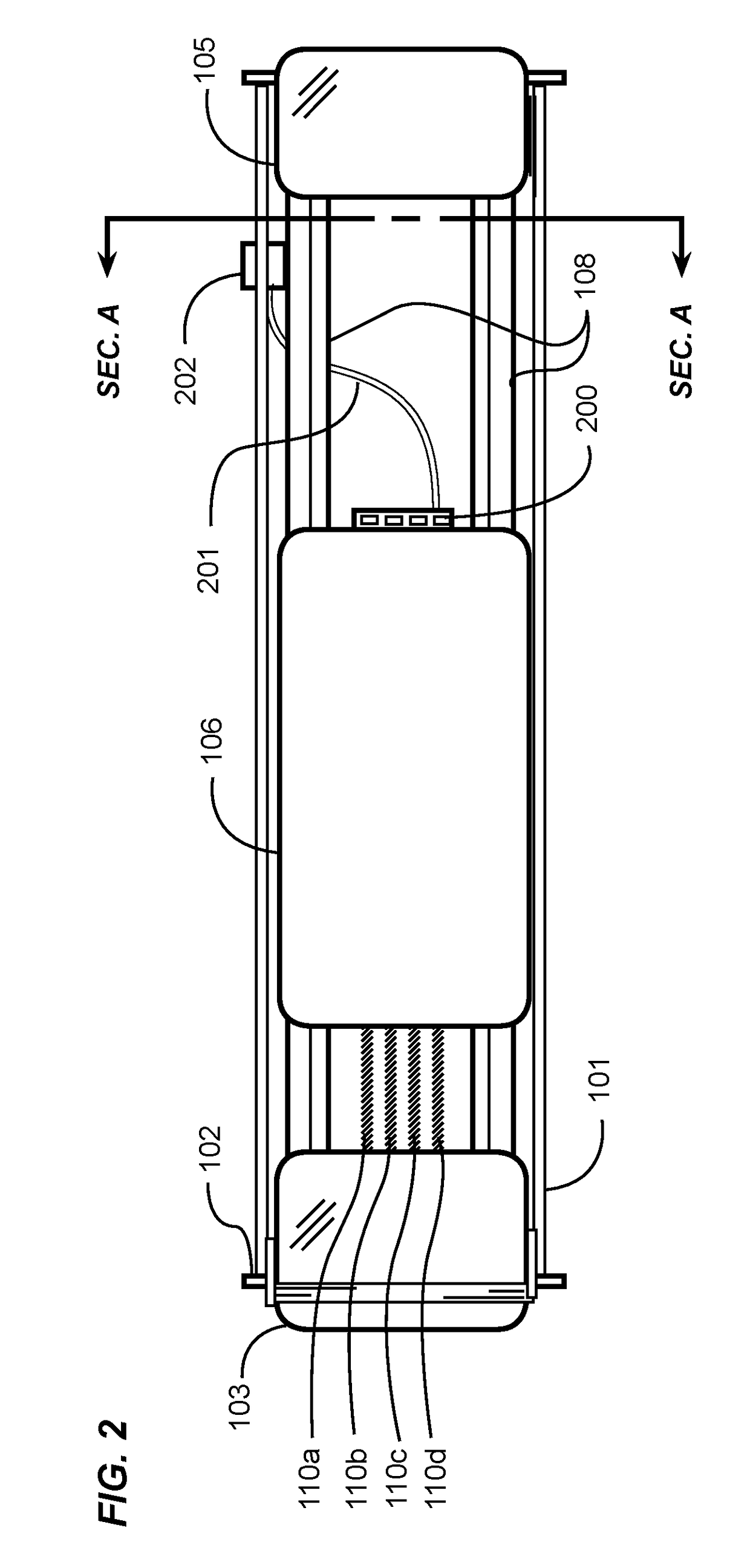
[0027]An example exercise machine with electromagnetic resistance selection generally comprises a movable carriage configured to move substantially along a length of at least one trolley rail supported on a machine structure; a plurality of resistance biasing members removably attachable between a stationary biasing member bracket affixed to the machine structure and the movable carriage; and a controller configured to change a resistance setting against the movable carriage by selectively electrically attaching or detaching any number of biasing members between the biasing member bracket and the movable carriage.

[0028]Various aspects of specific embodiments are disclosed in the following description and related drawings. Alternate embodiments may be devised without departing from the spirit or the scope of the present disclosure. Additionally, well-known elements of exemplary embodiments will not be described in detail or will be omitted so as not to obscure relevant de...


PUM


Abstract

An exercise machine with electromagnetic resistance selection for changing exercise resistance settings by engaging more or fewer resistance biasing members using a electromagnets. An example implementation includes a movable carriage configured to move substantially along the length of one or more rails. A plurality of resistance biasing members are removably attachable between a stationary biasing member bracket affixed to the machine structure and the movable carriage. A controller changes the resistance settings against the movable carriage by electrically attaching or detaching any preferred number of resistance biasing members between the machine structure and movable carriage.

Description

CROSS REFERENCE TO RELATED APPLICATIONS[0001]I hereby claim benefit under Title 35, United States Code, Section 119(e) of U.S. provisional patent application Ser. No. 62 / 361,211 filed Jul. 12, 2016. The 62 / 361,211 application is currently pending. The 62 / 361,211 application is hereby incorporated by reference into this application.STATEMENT REGARDING FEDERALLY SPONSORED RESEARCH OR DEVELOPMENT[0002]Not applicable to this application.BACKGROUNDField[0003]The present invention relates to the field of exercise and fitness training equipment. More specifically, the improved exercise machine provides for changing exercise resistance settings by engaging more or fewer resistance biasing members using an electromagnetic clutch.Related Art[0004]Any discussion of the related art throughout the specification should in no way be considered as an admission that such related art is widely known or forms part of common general knowledge in the field.[0005]Those skilled in the art will appreciate ...

Claims


Application Information

Patent Timeline
IPC IPC(8): A63B21/06A63B22/00A63B22/20A63B21/02A63B23/02
CPCA63B21/0615A63B21/023A63B23/02A63B22/0087A63B22/203A63B21/0052A63B21/0442A63B21/055A63B21/0552A63B22/0007A63B22/001A63B24/0087A63B2225/50A63B21/00065A63B21/4034A63B21/4035A63B21/4033A63B2209/08A63B2208/0219A63B22/0089A63B2024/0081A63B2225/20A63B21/00192A63B21/025
Inventor LAGREE, SEBASTIEN ANTHONY LOUISCOX, SAMUEL D.REMUND, TODD G.
Owner LAGREE TECH INC
Features
  • Generate Ideas
  • Intellectual Property
  • Life Sciences
  • Materials
  • Tech Scout
  • Unparalleled Data Quality
  • Higher Quality Content
  • 60% Fewer Hallucinations
Learn More