
Method and device for inverse tone mapping

Inactive Publication Date: 2018-04-26
THOMSON LICENSING SA
View PDF0 Cites 6 Cited by
  • Summary
  • Abstract
  • Description
  • Claims
  • Application Information

AI Technical Summary

Benefits of technology

The invention proposes to limit the brightness of shots in a high dynamic range (HDR) sequence when there are alternating bright and non-bright shots for short durations. The technical effect is to reduce glare and improve image quality in the HDR sequence.

Problems solved by technology

Despite the above-mentioned advantages of the HDR displays, it has been commonly noticed that viewers can be blinded by pictures presenting high peak of brightness especially inside dark rooms.
Therefore, viewers are distracted by some parts of bright image breaking the immersion from the movie action, even dazzled when watching a sequence of explosion scenes.
More specifically, HDR video sequences presenting transitions from dark to bright sequences generate a series of flash that cause eye strain for the viewers.
This discomfort is much higher as the frequency of alternating dark to bright scene is higher.
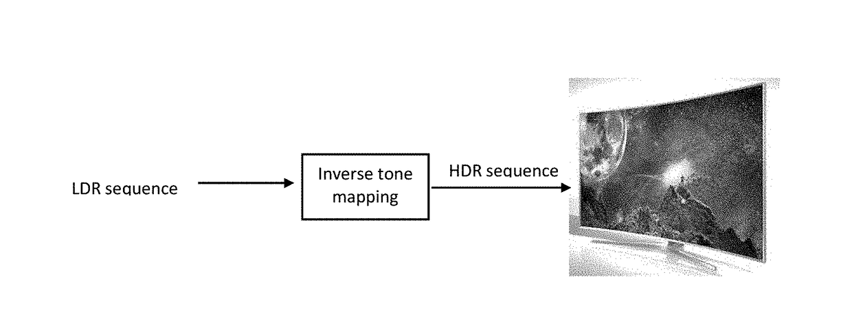
But this problem is not taken into account in the existent SDR to HDR conversion (or inverse tone mapping) process.

Method used


Image

  • Method and device for inverse tone mapping
  • Method and device for inverse tone mapping
  • Method and device for inverse tone mapping

Examples


Embodiment Construction

[0032]While example embodiments are capable of various modifications and alternative forms, embodiments thereof are shown by way of example in the drawings and will herein be described in detail. It should be understood, however, that there is no intent to limit example embodiments to the particular forms disclosed, but on the contrary, example embodiments are to cover all modifications, equivalents, and alternatives falling within the scope of the claims. Like numbers refer to like elements throughout the description of the figures.

[0033]Before discussing example embodiments in more details, it is noted that some example embodiments are described as processes or methods depicted as flowcharts. Although the flowcharts describe the operations as sequential processes, many of the operations may be performed in parallel, concurrently or simultaneously. In addition, the order of operations may be re-arranged. The processes may be terminated when their operations are completed, but may a...


PUM


Abstract

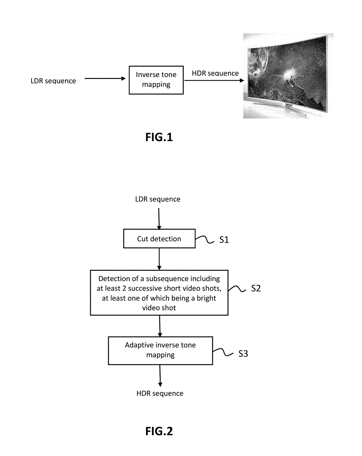
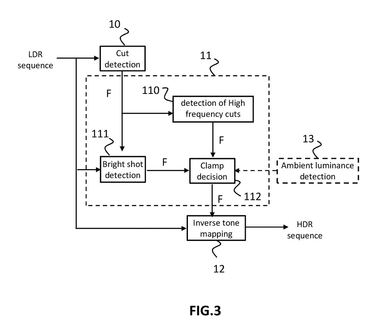
A method for converting a standard dynamic range (SDR) sequence into a high dynamic range (HDR) sequence is described. The method includes determining (S1) successive shots in the SDR sequence by cut detection, detecting (S2) if the SDR sequence comprises a sub-sequence of at least two successive short shots having a duration lower than D1, said subsequence comprising at least one bright shot having a luminance and a size greater than L1 and SZ1 respectively, and mapping (S3) the luminance range of bright shots of the detected subsequence from the low dynamic range to a first high dynamic range and mapping the other shots of the SDR sequence from the standard dynamic range to a second high dynamic range in order to generate the HDR sequence, the first high dynamic range having a maximal value Lmax1 lower than that of the second high dynamic range Lmax2.

Description

1. REFERENCE TO RELATED EUROPEAN APPLICATION[0001]This application claims priority from European Patent Application No. 16306378.7, entitled “METHOD AND DEVICE FOR INVERSE TONE MAPPING,” filed on Oct. 20, 2016, the contents of which are hereby incorporated by reference in its entirety.2. TECHNICAL FIELD[0002]The present invention relates generally to the field of inverse tone mapping.3. BACKGROUND ART[0003]Over the past years, High Dynamic Range (or HDR) displays have become more and more popular during the international electronics exhibitions. They offer a new user experience as they can show images and videos with high brightness (until 4000 nits) compared to standard or Standard Dynamic Range (SDR) displays (150-400 nits). HDR devices are able to display videos with more details in black levels and with a higher global contrast. Despite the growth of HDR video content, there is a need to display existing standard videos on HDR displays. For this purpose, inverse tone mapping ope...

Claims


Application Information

Patent Timeline
IPC IPC(8): H04N7/01H04N5/14G06T5/00G06T5/40
CPCH04N7/0125H04N5/147G06T5/009G06T5/40G06T2207/10016G06T2207/20208H04N23/70G06T5/92H04N23/71H04N25/57G06V20/49G06T5/90
Inventor GUERMOUD, HASSANETHEBAULT, CEDRICKERVEC, JONATHAN
Owner THOMSON LICENSING SA
Learn More