Multi-range hdr video coding

a video coding and multi-range technology, applied in image enhancement, image analysis, instruments, etc., can solve the problems of no elegant simple solution, no room available for anything overly bright, and not quite that simpl

Active Publication Date: 2021-11-18
KONINKLJIJKE PHILIPS NV
View PDF0 Cites 6 Cited by
  • Summary
  • Abstract
  • Description
  • Claims
  • Application Information

AI Technical Summary

Problems solved by technology

One may naively think that this is all there is to encoding and decoding HDR images, but things are not quite that simple, ergo additional coding approaches emerged, in particular the previously developed approach to HDR video coding and handling of the present applicant.
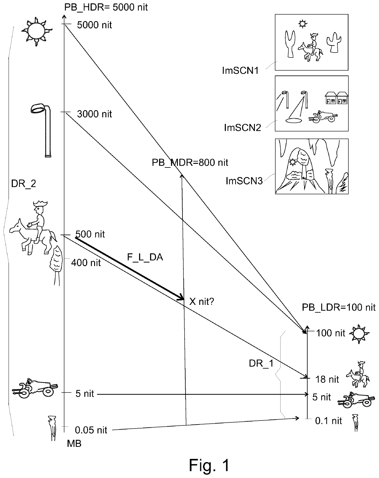
A problem with the natural HDR codec (which merely offers a technology to encode luminances up to 10,000 nit i.e. also up to 5000 nit as desired in this example), is that if the consumer also has an expensive 5000 nit display peak brightness (PB_D) display (and if he views the image under standardized viewing environment conditions) he may watch the video perfectly as the creator (e.g. the movie director) intended, but if he has a different display (e.g. PB_D=750 nit, or PB_D=100 nit) there is an unresolved, and also not simple problem: how does one display a 5000 nit PB_C image on a 750 nit PB_D display?
There seems to be no elegant simple solution to this.
And also, on a 100 nit TV or in a 100 nit encoding there just isn't any room available for anything overly bright.
The problem was that the Rec. 709 OETF could only code a luminance dynamic range of 1000:1, i.e. a new HDR OETF (or in fact its inverse, the EOTF) had to be invented.
A significant technical difficulty with HDR10 images is still how to appropriately display them on lesser capable displays (e.g. less capable than the 2000 PB_C that the HDR content was made for).
Because of the logarithmic nature of the PQ OETF, HDR10 images are watchable (when just rendered as lumas, i.e. decoded with the wrong EOTF), but have an ugly deteriorated contrast, making them look inter alia washed out and of incorrect brightness.
However, several other scenes may be more complex, and some content creators may also have a higher level of professional desiderata when fine-tuning their artistic content (e.g. a Hollywood movie director or DOP).
The problem when using a course luminance mapping function with too small a slope for the brightest pixels, is that the shadow man may become insufficiently contrasty and badly visible in lesser dynamic range images, such as the SDR image.
The difficulty is to always obtain the appropriate output chrominances, knowing that there are many difficulties: an irregularly shaped color gamut of realizable colors (see explanation in FIG. 5), non-linearities of the math, and otherwise of the human visual system of the viewers, etc.
Furthermore as will be shown below in the present application's embodiments, the market has ever more desiderata, leading to ever more complicated HDR handling systems.
A disadvantage, at least from the point of view of a content creator who would like that every consumer can see his movie as nicely as he originally created it, is that such a variability will create a high degree of uncertainty on what any particular brand television will make of any received HDR image.
Performing another simplistic tone mapping reinterpretation like e.g. a linear compression of the luminances like a white-on-white strategy can create several other problems.
Those are the typical HDR impact objects / effects, that however also are not reproducible correctly anyway since it is in the upper region of the luminance range that the various capability displays vary most.

Method used


Image

  • Multi-range hdr video coding
  • Multi-range hdr video coding
  • Multi-range hdr video coding

Examples


Embodiment Construction

"d_n">[0166]FIG. 9 shows generically the new SLHDR2PLUS encoder 900. As input it gets a master HDR image (e.g. a 5000 nit PB_C image MsterHDR), which without wanting to lose generality the reader can assume to have been made at or around the time of encoding by a human color grader using color grading software, e.g. by starting from a RAW camera-captured HDR image (the MsterHDR image being optimized e.g. for a typical evening dim television viewing environment, i.e. its average surround luminance etc.; the present technologies can also work with other or variable environments, but that is rather an issue of display adaptation rather than new methods to create or code HDR images). The grader has also created at least one nice luminance downgrading function FL_50t1, to convert the 5000 nit master HDR image in a corresponding nice looking SDR image (i.e. of usual 100 nit PB_C), and he has done this by filling in some of the partial re-grading aspects of 403, 404 and 405, and some good ...


PUM


Abstract

At least some applications in the total HDR video chain desire some more sophisticated approach, such as a high dynamic range video encoder (900), arranged to receive via an image input (920) an input high dynamic range image (MsterHDR) which has a first maximum pixel luminance (PB_C_H50), the encoder being arranged to receive via a metadata input (921) a master luma mapping function (FL_50t1), which luma mapping function defines the relationship between normalized lumas of the input high dynamic range image and normalized lumas of a corresponding standard dynamic range image (Im_LDR) having a maximum pixel luminance of preferably 100 nit, characterized in that the encoder further comprises a metadata input (923) to receive a second maximum pixel luminance (PB_CH), and the encoder further being characterized in that it comprises: —a HDR function generation unit (901) arranged to apply a standardized algorithm to transform the master luma mapping function (FL_50t1) into a adapted luma mapping function (F_H2hCI), which relates normalized lumas of the input high dynamic range image to normalized luminances of an intermediate dynamic range image (IDR) which is characterized by having a maximum possible luminance being equal to the second maximum pixel luminance (PB_CH); an IDR image calculation unit (902) arranged to apply the adapted luma mapping function (F_H2hCI) to lumas of pixels of the input high dynamic range image (MsterHDR) to obtain lumas of pixels of the intermediate dynamic range image (IDR); and an IDR mapping function generator (903) arranged to derive on the basis of the master luma mapping function (FL_50t1) and the adapted luma mapping function (F_H2hCI) a channel luma mapping function (F_I2sCI), which defines as output the respective normalized lumas of the standard dynamic range image (Im_LDR) when given as input the respective normalized lumas of the intermediate dynamic range image (IDR); the encoder being further characterized to have as output: the intermediate dynamic range image (IDR), as first metadata the second maximum pixel luminance (PB_CH), as second metadata the channel luma mapping function (F_I2sCI); and as third metadata the first maximum pixel luminance (PB_C_H50).

Description

FIELD OF THE INVENTION[0001]The invention relates to methods and apparatuses for coding high dynamic range images, and in particular videos being time sequences of images which can be compressed according to compression techniques like MPEG-HEVC (e.g. television broadcasts), in particular by using an image(s) of a second dynamic range (for communication to a decoder) to represent a (master) image(s) of a first dynamic range, which dynamic range change involves the changing of image pixel luminances (e.g. from a first normalized to 1.0 value to a second normalized to 1.0 value) by applying functions to be co-communicated with the second dynamic range image(s) typically as metadata.BACKGROUND OF THE INVENTION[0002]About 5 years ago, the novel techniques of high dynamic range video coding were introduced to the world (e.g. leading to special HDR blu-ray disks, to be watched on 1000 nit UltraHD Premium tv's).[0003]This novel way of technically handling images contrasts technically in ma...

Claims


Application Information

Patent Timeline
Patent Type & Authority Applications(United States)
IPC IPC(8): H04N19/186H04N19/98H04N19/44
CPCH04N19/186H04N19/44H04N19/98H04N19/46G06T5/009G06T2207/10024G06T2207/20208
Inventor VAN DER VLEUTEN, RENATUS JOSEPHUSNIJLAND, RUTGERTICHELAAR, JOHANNES YZEBRAND
Owner KONINKLJIJKE PHILIPS NV
Why Eureka
Try Eureka