
Three-dimensional display device and three-dimensional display method

Active Publication Date: 2018-05-17
BOE TECH GRP CO LTD
View PDF0 Cites 0 Cited by
  • Summary
  • Abstract
  • Description
  • Claims
  • Application Information

AI Technical Summary

Benefits of technology

The present disclosure provides a method for reducing Moire and crosstalk deficiencies in a parallax-barrier-type 3D display device. The method includes enabling the image to translate in the viewer's vicinity and adjusting a light-through stripe pattern within the parallax barrier based on the positions of the viewer's eyes. This results in the effective suppression of Moire and crosstalk deficiencies, improving the display effect of the 3D display device.

Problems solved by technology

Specifically, crosstalk is generated due to the fact that light rays for left-eye images and light rays for right-eye images cannot be completely separated between the left eye and the right eye of a viewer, which results in a ghost image in both eyes of the viewer and a significant deterioration on the display effect.
However, light rays may well easily scatter towards other directions through openings (light-through sections) of the parallax barrier.
Such a crosstalk phenomenon cannot be eliminated easily in the prior art.
On the other hand, due to their proximity in terms of spatial frequency between the parallax barrier and pixel arrangement, this type of 3D display device is also subject to severe Moire phenomenon in the meantime.

Method used


Image

  • Three-dimensional display device and three-dimensional display method
  • Three-dimensional display device and three-dimensional display method
  • Three-dimensional display device and three-dimensional display method

Examples


Embodiment Construction

[0035]In order to make the present disclosure more clear, embodiments of the present disclosure will be clearly and fully described hereinafter in conjunction with the accompanying drawings. Obviously, the described embodiments are merely parts of embodiments of the present disclosure, but not all the embodiments. Based on the embodiments in the present disclosure, all the other embodiments obtained by a person skilled in the art will fall within the protection scope of the present disclosure.

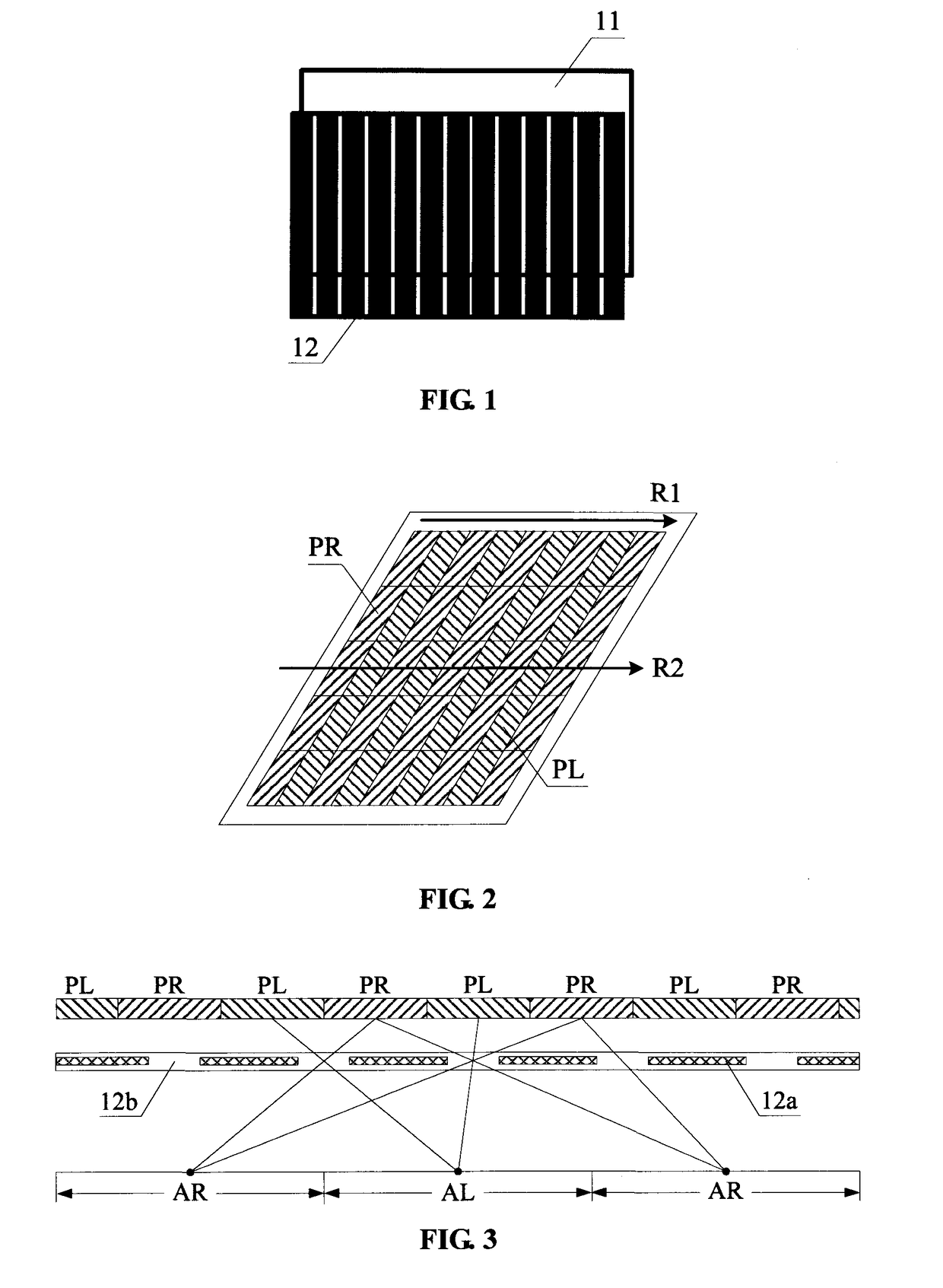
[0036]FIG. 1 is a structural diagram illustrating a three-dimensional (3D) display device according to a certain embodiment of the present disclosure. As shown in FIG. 1, the 3D display device includes a display panel 11 and a parallax barrier layer 12 disposed thereon. It should be noted that the display panel 11 and the parallax barrier 12 are illustrated as detached from each other for the sake of clarity, as shown in FIG. 1. However, the display panel 11 and the parallax barrier 12 are inte...


PUM


Abstract

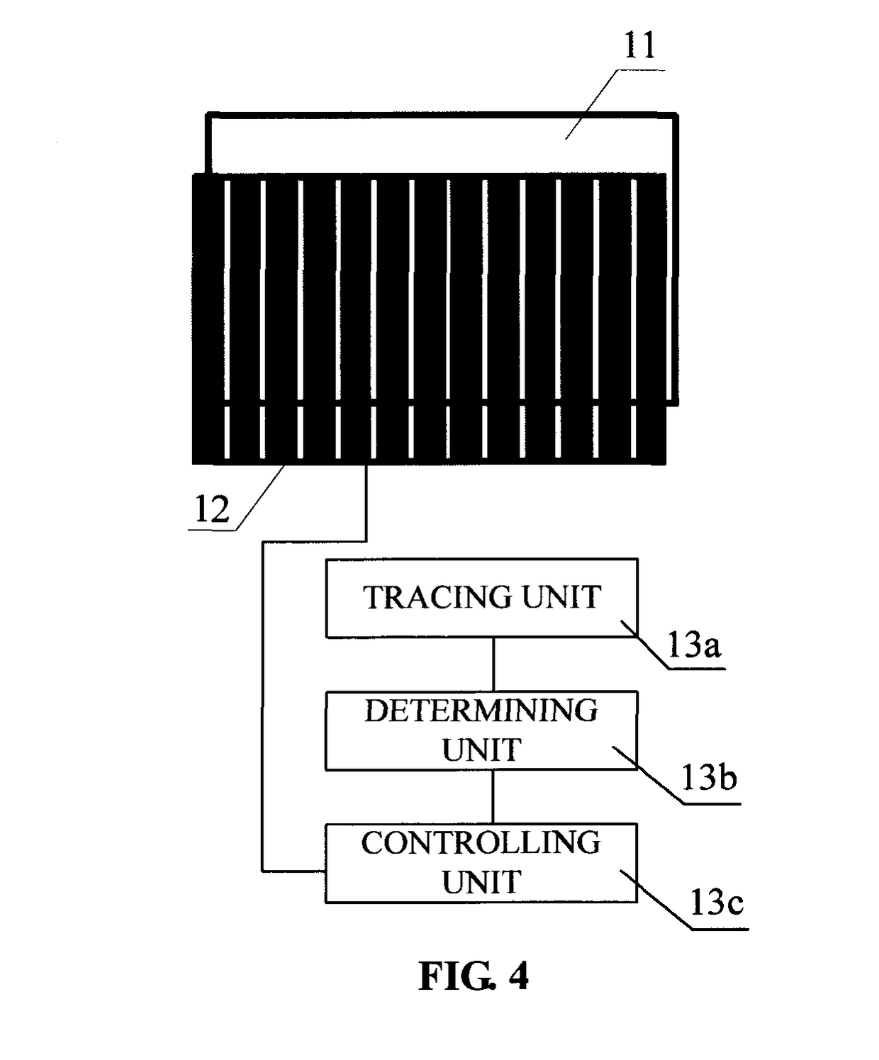
A three-dimensional display device may include a display panel and a parallax barrier layer arranged thereon. The display panel includes left-eye pixels and right-eye pixels arranged alternately in a first direction. The 3D display device may further include: a tracing unit configured to trace positions of both eyes of a viewer; a determining unit coupled to the tracing unit and configured to determine an offset of the light-shield stripe pattern with respect to a predetermined baseline position in a second direction under a predetermined condition, based on the positions of both eyes of the viewer obtained by the tracing unit; and a controlling unit coupled to the determining unit and configured to transmit a control signal to the parallax barrier layer based on the offset obtained, such that the light-shielding stripe pattern formed by the parallax barrier layer is translatable in the second direction based on the offset.

Description

CROSS REFERENCE TO RELATED APPLICATIONS[0001]This application is a National Stage Entry of PCT / CN2015 / 098244, filed Dec. 22, 2015, which claims priority to Chinese Patent Application No. 201510463447.7, filed on Jul. 31, 2015, the disclosure of each of which is incorporated herein by reference in its entirety.BACKGROUND[0002]The present disclosure relates to the field of display technology, and in particular to a three-dimensional (3D) display device and a 3D display method.[0003]In a conventional naked-eye three-dimensional (3D) displaying, crosstalk and Moire are two main deficiencies which deteriorate the 3D display effect. Specifically, crosstalk is generated due to the fact that light rays for left-eye images and light rays for right-eye images cannot be completely separated between the left eye and the right eye of a viewer, which results in a ghost image in both eyes of the viewer and a significant deterioration on the display effect. For example, in a conventional parallax-b...

Claims


Application Information

Patent Timeline
IPC IPC(8): G02B27/22G02B30/31
CPCH04N13/31H04N13/383H04N13/398H04N13/0484H04N13/0409H04N2213/001H04N13/0497G02B27/2214H04N13/366H04N13/317G02B30/31G02B30/27
Inventor WEI, WEI
Owner BOE TECH GRP CO LTD
Learn More