Transport device and rack mounted thereon

a technology for transporting devices and objects, applied in the direction of vehicle position/course/altitude control, process and machine control, instruments, etc., can solve the problem of unstable positioning of the devi

Inactive Publication Date: 2018-05-24
PANASONIC INTELLECTUAL PROPERTY MANAGEMENT CO LTD
View PDF1 Cites 18 Cited by
  • Summary
  • Abstract
  • Description
  • Claims
  • Application Information

AI Technical Summary

Benefits of technology

[0006]According to the configuration described above, the present disclosure can control the posture o...

Problems solved by technology

However, PTL 1 has such a problem that, during transportation of a mounted ob...

Method used


Image

  • Transport device and rack mounted thereon
  • Transport device and rack mounted thereon
  • Transport device and rack mounted thereon

Examples


first exemplary embodiment

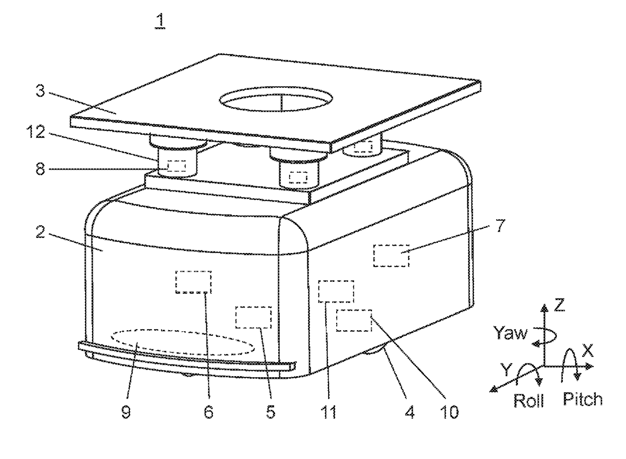
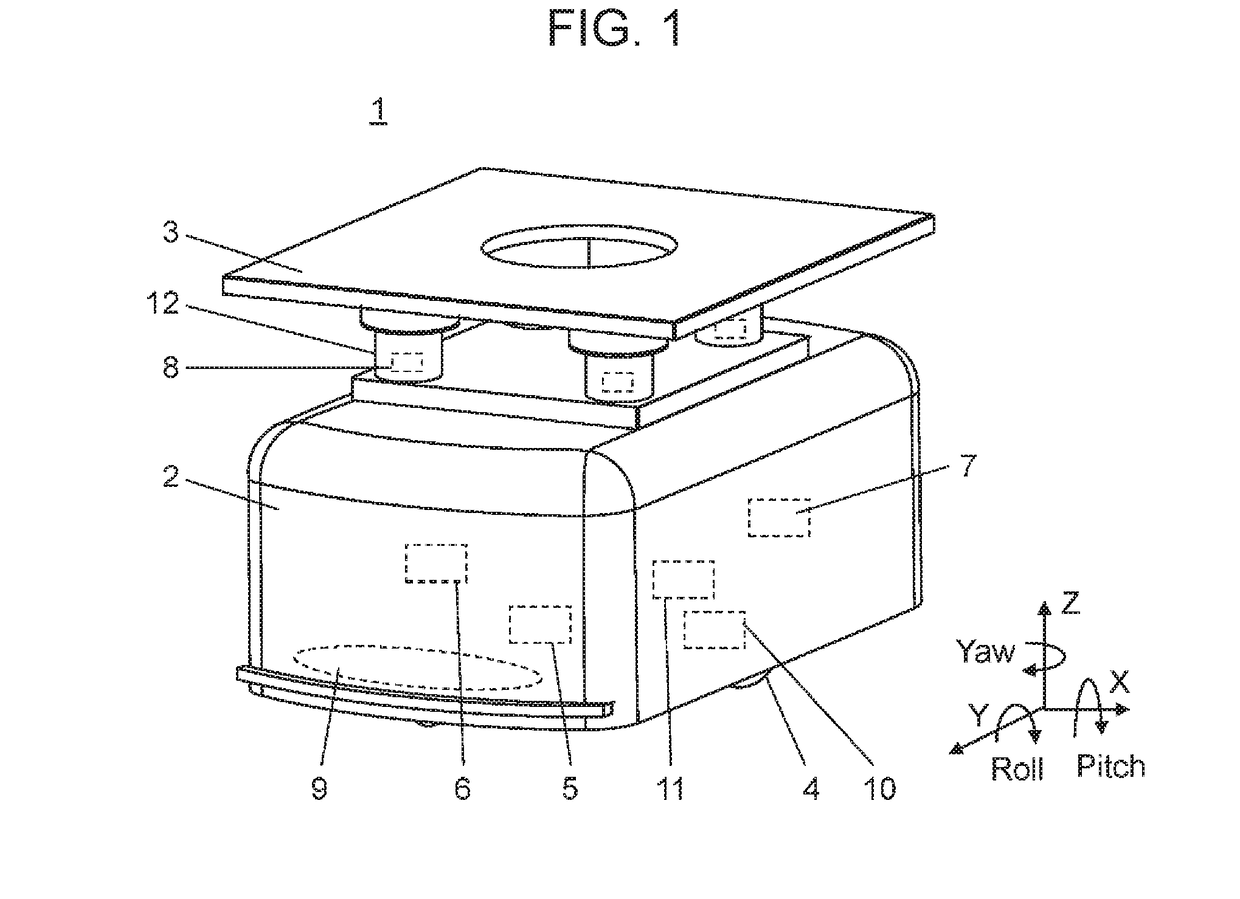
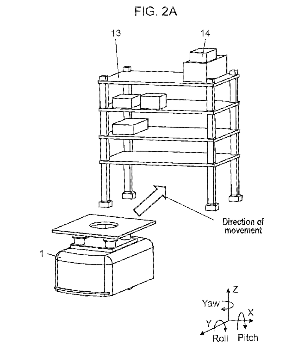
[0014]Hereinafter, transport device 1 according to the first exemplary embodiment, rack 13, and loaded object 14 will be described with reference to the drawings. Herein, a mounted object includes rack 13 and loaded object 14. In the following description, a direction of a side surface of the main body section 2 of transport device 1 is defined as an X-axis direction, a direction of movement of transport device 1 is defined as a Y-axis direction, and a direction of movement of base 3 of transport device 1 is defined as a Z-axis direction.

[0015]FIG. 1 is a perspective view of transport device 1 according to the first exemplary embodiment of the present disclosure. FIG. 2A is a view illustrating a state where transport device 1 advances toward rack 13, in which an arrow indicates a direction of movement of transport device 1. FIG. 2B is a view illustrating a state where transport device 1 lifts up rack 13, in which arrows indicate lifting of rack 13 and a direction of movement of tran...

second exemplary embodiment

[0028]Hereinafter, a device and a rack according to the second exemplary embodiment will be described with reference to the drawings. In the following description, one direction of the side surface of the rack is defined as an X-axis direction and a Y-axis direction, and the vertical direction of the rack is defined as a Z-axis direction.

[0029]FIG. 6 is a view illustrating the rack according to the second exemplary embodiment.

[0030]Device 1 of the second exemplary embodiment receives a signal from rack 21 to be transported to perform more optimum control for device 1. Device 1 further includes a wireless unit (not illustrated) for communicating with rack 21.

[0031]Rack 21 is constituted by four legs 22 and a plurality of shelves 23. Rack 21 is provided with weight sensors 24, angular speed sensor 25, acceleration sensor 26, and wireless unit 27 for communicating with device 1.

[0032]Device 1 according to the second exemplary embodiment is provided with a communication unit (not illust...


PUM


Abstract

A transport device includes a main body section, a base connected to the main body section, a wheel connected to the main body section for causing the transport device to travel, a drive module for driving the wheel, and a sensor that detects a state of the transport device, wherein a posture of the main body section is controlled using an output of the sensor such that the center of gravity of a mounted object approaches the center of gravity of the transport device.

Description

TECHNICAL FIELD[0001]The present disclosure relates to a device for transporting a loaded object while controlling a posture.BACKGROUND ART[0002]Conventionally, a device which has a main body section having wheels and a base attached to the main body section, and which automatically travels with a mounted object being mounted on the base has been embodied (see PTL 1).CITATION LISTPatent Literature[0003]PTL 1: Japanese Patent No. 5138681SUMMARY OF THE INVENTION[0004]However, PTL 1 has such a problem that, during transportation of a mounted object, the posture of the device is not stable with the mounted object being mounted.[0005]To address the foregoing problem, a transport device according to the present disclosure includes a device main body section for mounting a mounted object thereon, and a sensor that detects a state of the device main body section with the mounted object being mounted thereon. The device main body section has a base connected to the device main body section f...

Claims


Application Information

Patent Timeline
IPC IPC(8): B65G1/137B61B13/02B65G1/10B66F9/07
CPCB65G1/137B61B13/02B65G1/10B66F9/07B65G2203/042B65G1/00B66F7/22B66F9/063G05D1/0891G05D2201/0216
Inventor NAKANISHI, TSUTOMUUEMURA, TAKESHINAKAO, YORIKOAKIYOSHI, TAKAHIRO
Owner PANASONIC INTELLECTUAL PROPERTY MANAGEMENT CO LTD
Why Eureka
Try Eureka