Lighting apparatus

a technology of lighting apparatus and light source, which is applied in the direction of lighting and heating apparatus, light source combinations, fixed installations, etc., can solve the urgent problem of improving the visual environment achieved by lighting, and achieve the effects of avoiding glare, reducing intraocular scattering, and highly vivid colors

Active Publication Date: 2018-07-26
PANASONIC INTELLECTUAL PROPERTY MANAGEMENT CO LTD
View PDF1 Cites 5 Cited by
  • Summary
  • Abstract
  • Description
  • Claims
  • Application Information

AI Technical Summary

Benefits of technology

[0006]Taking (b) into consideration, there is also a method of adjusting a color-variable wall in order to reduce intraocular scattering due to ambient light, as disclosed in Japanese Unexamined Patent Application Publication No. 2005-302500.
[0007]Here, since it is regarded that the brightness necessary for old aged people to perform visual tasks is 2 to 5 times that for younger people, there has been a demand for a lighting apparatus which allows old aged people to perceive highly vivid colors while avoiding glare.
[0008]Furthermore, there has also been a demand for a lighting apparatus capable of emitting bright light over a wide area, in an area surrounding an area in which old aged people perform visual tasks.
[0009]In view of this, the present disclosure provides a lighting apparatus which prevents letters and observed objects from appearing to have lower readability and color saturation to old aged people, and emits bright light over a wide area.
[0010]A l

Problems solved by technology

In particular, improvement of visual environ

Method used


Image

  • Lighting apparatus
  • Lighting apparatus
  • Lighting apparatus

Examples


embodiment

[0034][Configuration]

[0035]First, the configuration of lighting apparatus 10 according to this embodiment will be described using FIG. 1 to FIG. 3.

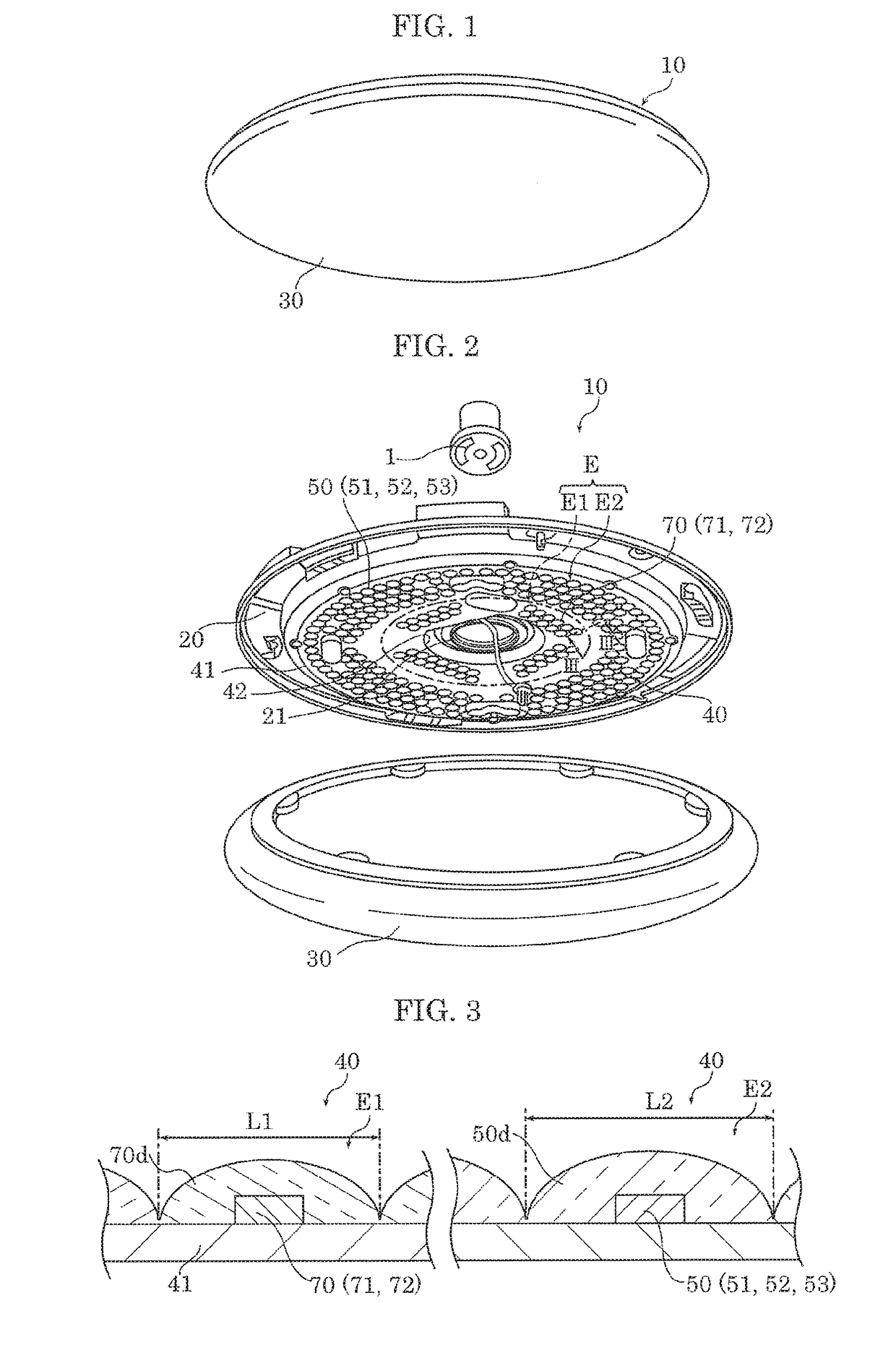
[0036]FIG. 1 is a perspective view of lighting apparatus 10 according to this embodiment. FIG. 2 is an exploded perspective view of lighting apparatus 10 according to this embodiment. FIG. 3 is a cross-sectional view of lighting apparatus 10 according to this embodiment taken along line III-III in FIG. 2.

[0037]As illustrated in FIG. 1 and FIG. 2, lighting apparatus 10 includes device body 20, cover 30, and light emitter 40. Lighting apparatus 10 is detachably attached to, for example, hook ceiling body 1 provided in the ceiling of a building such as a house, for example.

[0038]Device body 20 is a casing for supporting cover 30 and light emitter 40. Device body 20 is formed in a ring shape having circular opening 21 in the center portion. Hook ceiling body 1 is connected to light emitter 40 via opening 21.

[0039]It should be noted that devic...


PUM


Abstract

A lighting apparatus includes first light emitting elements and second light emitting elements, and a control circuit. The first light emitting elements the second light emitting elements are dispersedly disposed in a predetermined region. The first light emitting elements are more densely disposed in a periphery portion than in a center portion of the predetermined region. The second light emitting elements are more densely disposed in the center portion than in the periphery portion of the predetermined region.

Description

CROSS REFERENCE TO RELATED APPLICATION[0001]This application claims the benefit of priority of Japanese Patent Application Number 2017-011723 filed on Jan. 25, 2017, the entire content of which is hereby incorporated by reference.BACKGROUND1. Technical Field[0002]The present disclosure relates to a lighting apparatus, and in particular to a lighting apparatus for correcting a change in visual performance due to aging.2. Description of the Related Art[0003]With the arrival of an aging society, there has been a great demand for a comfortable environment for old aged people (middle aged generation and over). In particular, improvement of visual environment achieved by lighting is an urgent issue. As such, it is thus necessary to clarify how lighting can correct a change in human visual system caused by aging. Examples of a change in visual performance due to aging mainly include (a) a fall in transmittance of a crystalline lens, in particular a fall in transmittance of a crystalline le...

Claims


Application Information

Patent Timeline
IPC IPC(8): H05B33/08F21V5/00H05B44/00
CPCH05B33/0845F21V5/007F21Y2105/18F21Y2115/10F21S8/04F21V7/22F21V19/0015F21V3/02F21V19/00F21V23/04F21Y2105/12F21Y2113/13H05B45/24H05B45/20
Inventor HARADA, KAZUKIMATSUBAYASHI, YOKOTACHINO, YOUJIYAMADA, MAKOTO
Owner PANASONIC INTELLECTUAL PROPERTY MANAGEMENT CO LTD
Why Eureka
Try Eureka