Riser separation system

Active Publication Date: 2018-08-02
TECH PRECESS TECH INC
View PDF3 Cites 9 Cited by
  • Summary
  • Abstract
  • Description
  • Claims
  • Application Information

AI Technical Summary

Benefits of technology

[0016]The methods and apparatus disclosed herein provide improved gas catalyst separation efficiency due to contouring of the central riser rector outlet to provide a complete 180° turn and smoother flow into separation chambers. The smoother flow results in better vapor/catalyst flow patterns and hydraulics (i.e., reduced turbulence, flow pulsations and fluctuations at riser exit) being generated for improved gas solid separation. The new curved riser reactor outlet section and riser outlet cone-shaped concave deflector helps solid particles to flow along the walls of the riser reactor and central riser reactor outlet as it evacuates the riser reactor and allows gas to separate while catalyst is taking a smooth 180° turn.
[0017]The claimed apparatus allows for a very compact design, i.e., reduction in size such as 20-25% reduction in diameter and 10-15% reduction in height compared to the prior art. The more compact design of the claimed apparatus can be advantageously used to replace older systems and allow the enclosing vessel to be reused while increasing unit capacity. Further, the compact design reduces post riser residence time, thereby reducing

Problems solved by technology

Once the mixture leaves the riser reactor, less intimate contact can occur in the containment/separation vessel and undesirable thermal cracking reactions can occur which lead to the loss of valuable products and generation of low value by-products.
The inlet to the separating chamber has a severe 900 turn from the riser top and provides only a ¼ turn for gas and catalyst to separate from each other resulting in low separation efficiency.
There is no connection between the separating chambers creating the potential for uneven pressure distribution resulting in uneve

Method used


Image

  • Riser separation system
  • Riser separation system
  • Riser separation system

Examples


Example

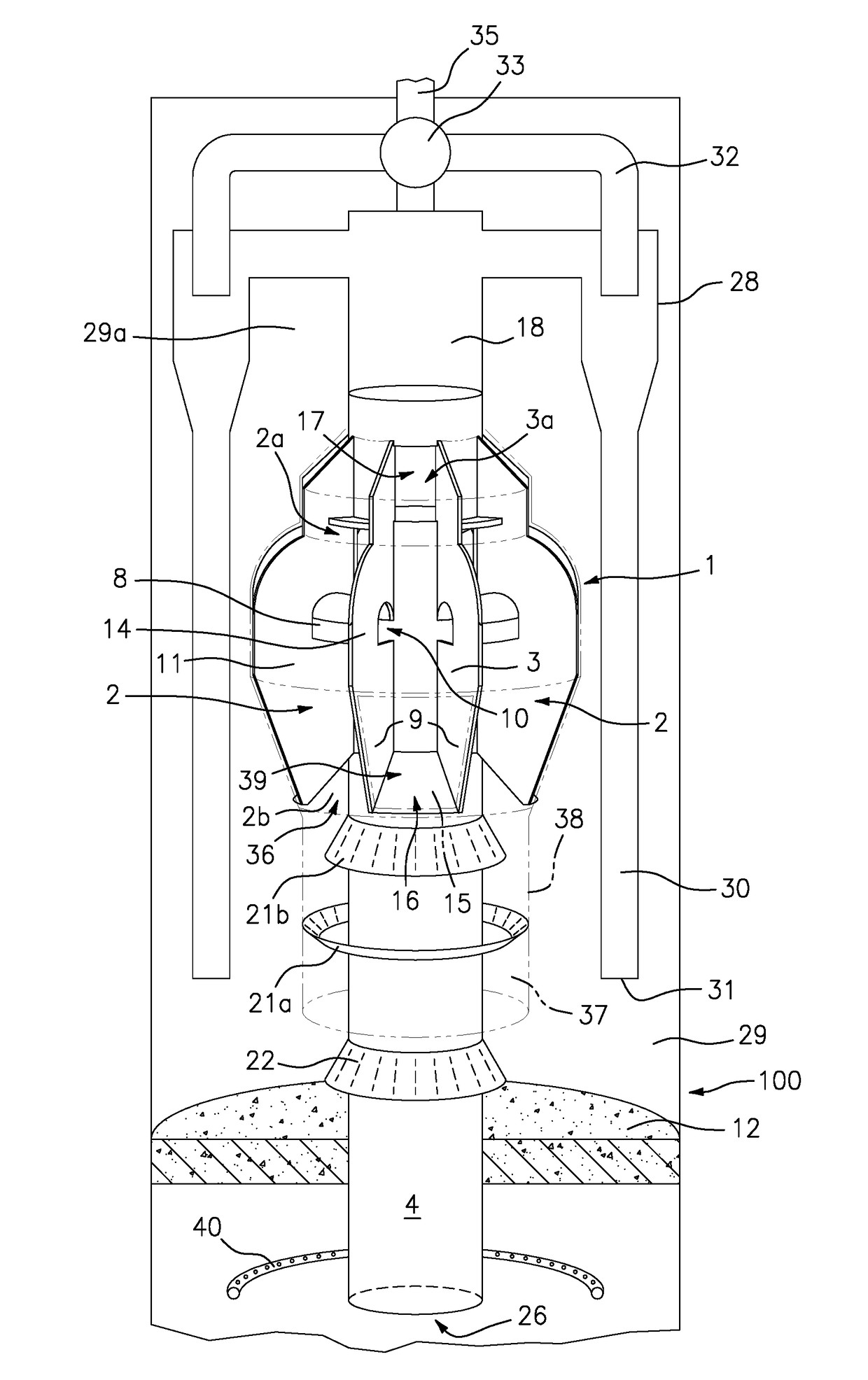
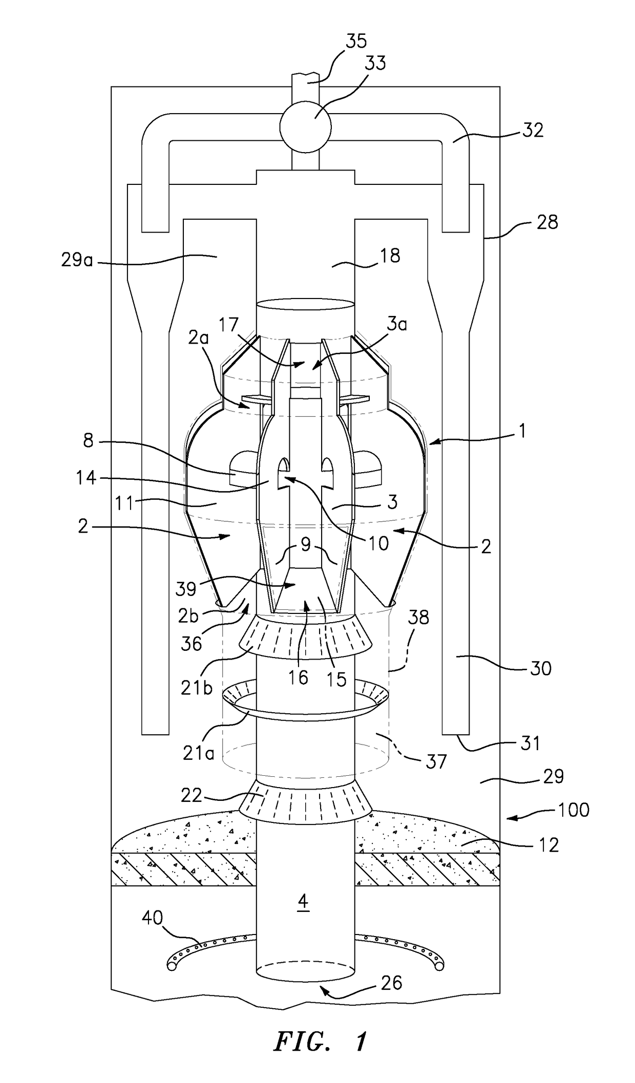
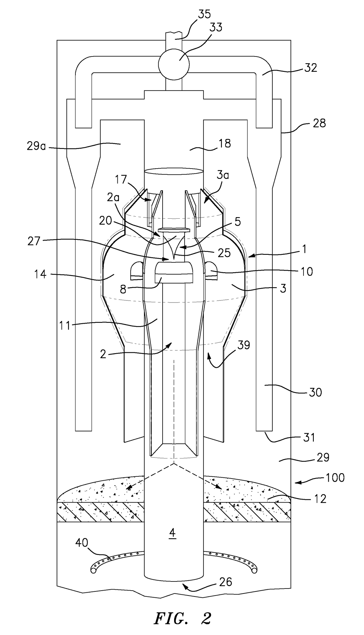
[0027]As more fully explained with reference to the Figures herein below, the improved apparatus for separating the cracked hydrocarbon vapor from FCC catalyst comprises a riser separation system that provides gas-solids separation efficiency, gas containment and stability of operation. The claimed apparatus provides rapid and improved gas catalyst separation and enhanced gas collection efficiency, however, as the separation vessel can be made smaller, residence time is reduced and undesired post riser thermal cracking is reduced providing additional performance benefits.

[0028]As more fully described below in one embodiment the claimed apparatus has a unique contouring of the central riser reactor outlet utilizing a smooth 180° transition for the cracked gases and solid particles that minimizes the turbulent flow regime in the central riser reactor outlet. Additional embodiments of the riser separation system include multiple collection chambers in conjunction with separation chambe...


PUM

PropertyMeasurementUnit
Temperatureaaaaaaaaaa
Angleaaaaaaaaaa

Abstract

The present disclosure is directed to an apparatus and a compact riser separation system for separating a gaseous mixture from a stream of particles entering from a central riser reactor used for cracking a hydrocarbon feed with the stream of particles. The apparatus provides improved gas solid separation efficiency and maximize containment of the hydrocarbon and minimize residence time in the separation system and thereby minimizing undesired post riser cracking reactions.

Description

FIELD OF THE INVENTION[0001]The embodiments disclosed herein relate to any vapor-particulate operations using a high velocity, dilute phase lift line (or riser reactor), such as the Fluid Catalytic Cracking (FCC) process. In such processes there is a need for an improved apparatus for separating the catalyst and vapor phases via a Reaction Termination Device (RTD) at the riser reactor exit. In addition to vapor-solid separation, the RTD should also provide a way to minimize the residence time of the separated vapor to prevent undesired post riser reactor reactions. In the present apparatus the vapor-catalyst mixture is routed through a series of unique contours and chambers providing a smooth flow profile that promote gas solid separation. The separation device also maximizes the containment of the vapor and, due to its very compact design, the vapor residence time reduces within the system. It is also desirable the design addresses the inherent imbalances of flow that can arise in ...

Claims


Application Information

Patent Timeline
IPC IPC(8): C10G11/18B01D45/08B01J8/18B01J8/00B01J19/00
CPCC10G11/18B01D45/08B01J2208/00761B01J8/005B01J19/006B01J8/1872B01J8/0055B01J8/0065B01D45/06E21B43/34
Inventor MARCHANT, PAULSINGH, RAJ KANWAR
Owner TECH PRECESS TECH INC
Why Eureka
Try Eureka