
Anti-Glare Device and Method for Automobiles

Inactive Publication Date: 2018-08-16
DING TIANHAO
View PDF0 Cites 0 Cited by
  • Summary
  • Abstract
  • Description
  • Claims
  • Application Information

AI Technical Summary

Benefits of technology

The invention is an anti-glare device that reduces headlight glare from approaching automobiles at night. The device includes a thin strip of tinted material that is installed on the driver's sun visor using a simple attachment mechanism. The anti-glare panel is designed to be very small in size so that drivers can maintain maximum natural vision of the external scene and to maximize the safety of the driver in the event of an accident or sudden stop. The device is easy to install and is made of light and flexible parts that are relatively easy and inexpensive to manufacture. The attachment mechanism is an elastic member that allows the panel to easily slide on the string, allowing the driver to adjust its lateral position. Additionally, the anti-glare panel can decrease over its horizontal length, forming a recess at its bottom corner for allowing natural visibility of a center line and / or lane markings of the road.

Problems solved by technology

These rigid parts are a safety hazard in the event of an accident.
Additionally, the complex attachment mechanisms make the devices difficult and expensive to manufacture, and difficult install.
For example, sunlight results in glare that is either uniformly distributed in parallel beams or reflected from varied, unpredictably distributed sources (such as car windows, building windows, street signs, bodies of water, etc.).
At night, the glare from approaching headlights can severely obstruct a driver's vision.
This is discomforting and distracting to drivers and could lead to automobile accidents.

Method used


Image

  • Anti-Glare Device and Method for Automobiles
  • Anti-Glare Device and Method for Automobiles
  • Anti-Glare Device and Method for Automobiles

Examples


first embodiment

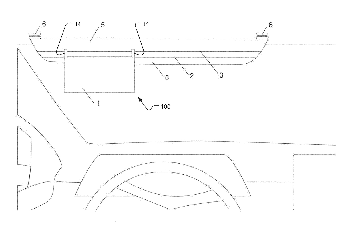
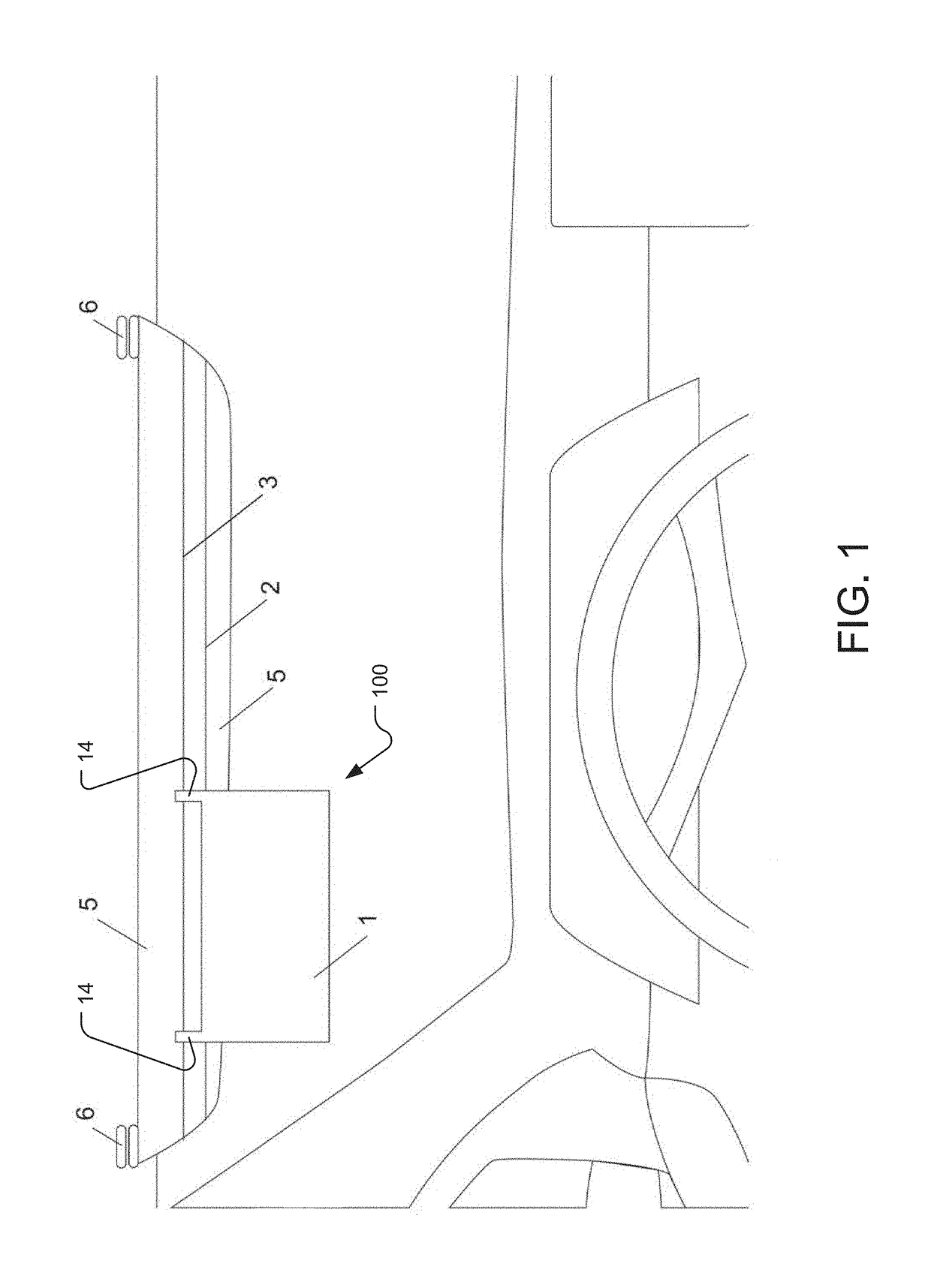
[0030]FIG. 1 shows an device 100 according to the present invention.

[0031]Here, the anti-glare device 100 is installed on a sun visor 5 of an automobile. In a typical automobile, the sun visor 5 is attached to the ceiling of the automobile via one or more visor attachment mechanisms 6, which typically comprise hinges and / or clips for tilting the sun visor 5 forward, backward, left and / or right. In the illustrated example, the visor attachment mechanisms 6 attach to the top edge of the sun visor 5.

[0032]In the illustrated example, the anti-glare device 100 includes an anti-glare panel 1, which is a strip of tinted, transparent film, and an attachment mechanism comprising a primary elastic member 3 (e.g. an elastic string or an elastic band) and a secondary elastic member 2. In general, the attachment mechanism secures the anti-glare panel 1 to the sun visor 5, and the anti-glare panel 1 reduces glare by attenuating and / or filtering the light traveling from the source of glare through...

second embodiment

[0045]FIG. 3 illustrates an example of the anti-glare device 100. In this example, the attachment mechanism further comprises two U-shaped clips 4. Instead of joining together to form a ring, each end of the primary elastic member 3 attaches to one of the U-shaped clips 4. The U-shaped clips then attach to the left and right side edges of the sun visor 5, securing the anti-glare device 100 in place.

[0046]FIG. 4 illustrates an example of the second embodiment of the anti-glare device 100 comprising the U-shaped clips 4, wherein the anti-glare panel 1 is secured in an inactive position by the secondary elastic member 2.

[0047]FIG. 5 is an image of the first embodiment of the anti-glare device 100. In the image, the device is not installed. Depicted are the anti-glare panel 1, the attachment arms 14 and the primary elastic member 3.

third embodiment

[0048]FIG. 6 is an image of the anti-glare device 100. In the depicted embodiment, the horizontal length of the anti-glare panel 1 decreases over the vertical width of the anti-glare panel 1, forming a recess 15 at the bottom right corner of the panel. Now the anti-glare panel 1 can be positioned such that light from the center of the road does not pass through the anti-glare panel 1 and thus reaches the driver's eye without being filtered or attenuated. In this way, the recess 15 allows for natural visibility of the center line and / or lane markings of the road by not obscuring or reducing the intensity of light coming from the region of the driver's visual field most likely to contain the center line and / or lane markings.


PUM


Abstract

An anti-glare device for reducing night-time road glare includes an anti-glare panel for attenuating and / or filtering light traveling from a source of glare through the panel to a driver's eyes. The anti-glare panel is secured to a sun visor of an automobile via an attachment mechanism comprising an elastic member, which compresses around the sun visor. The anti-glare panel attaches to the elastic member via attachment arms of the anti-glare panel that are folded over and secured, forming loops through which the elastic member is threaded. The attachment mechanism can further comprise a secondary elastic member for holding the anti-glare panel in an inactive position when the device is not being used. Additionally, the horizontal width of the anti-glare panel can decrease over the panel's vertical length, forming a recess at the panel's bottom corner for allowing natural visibility of a center line and / or lane markings of the road.

Description

RELATED APPLICATIONS[0001]This application claims the benefit under 35 USC 119(e) of U.S. Provisional Application No. 62 / 457,876, filed on Feb. 11, 2017, which is incorporated herein by reference in its entirety.BACKGROUND OF THE INVENTION[0002]Glare, from sources such as direct sunlight and reflections of sunlight during the day, and bright headlights at night, can negatively affect visibility for drivers of automobiles.[0003]Several anti-glare devices have been implemented to block or reduce glare. Typically, existing anti-glare devices attach to a sun visor of the automobile using hooks or clips and comprise anti-glare panels, which are panels of either tinted, translucent or opaque material for filtering, selectively blocking, or entirely blocking light from reaching the eyes of the driver, thus reducing glare.SUMMARY OF THE INVENTION[0004]Existing anti-glare devices include parts that are rigid, such as anti-glare panels that are thick and inflexible, and attachment mechanisms ...

Claims


Application Information

Patent Timeline
IPC IPC(8): B60J3/02
CPCB60J3/0208B60J3/0291B60J3/0234
Inventor DING, TIANHAO
Owner DING TIANHAO
Features
  • Generate Ideas
  • Intellectual Property
  • Life Sciences
  • Materials
  • Tech Scout
  • Unparalleled Data Quality
  • Higher Quality Content
  • 60% Fewer Hallucinations
Learn More