Method for pipe coupling encapsulation

Active Publication Date: 2018-08-16
KRAUSZ IND
View PDF5 Cites 0 Cited by
  • Summary
  • Abstract
  • Description
  • Claims
  • Application Information

AI Technical Summary

Benefits of technology

[0007]The present invention seeks to provide an improved method for pipe coupling encapsulation, as is described more in detail further below. Unlike the prior art, in the present invention, the seals on either side of the leak are not permanently attached to the inside of the two metal half-rings or the metal band. Instead, the seal is an elastomeric partial ring that is wrapped or otherwise placed around the pipe

Problems solved by technology

Thus replacement of a faulty pipe joint is not an option.
Prior art seals are not capable of being used externally over an existing coupling or existing bell joint.
Prior art seals lack the internal space needed if the repair seal is to be applied over and

Method used


Image

  • Method for pipe coupling encapsulation
  • Method for pipe coupling encapsulation
  • Method for pipe coupling encapsulation

Examples


Example

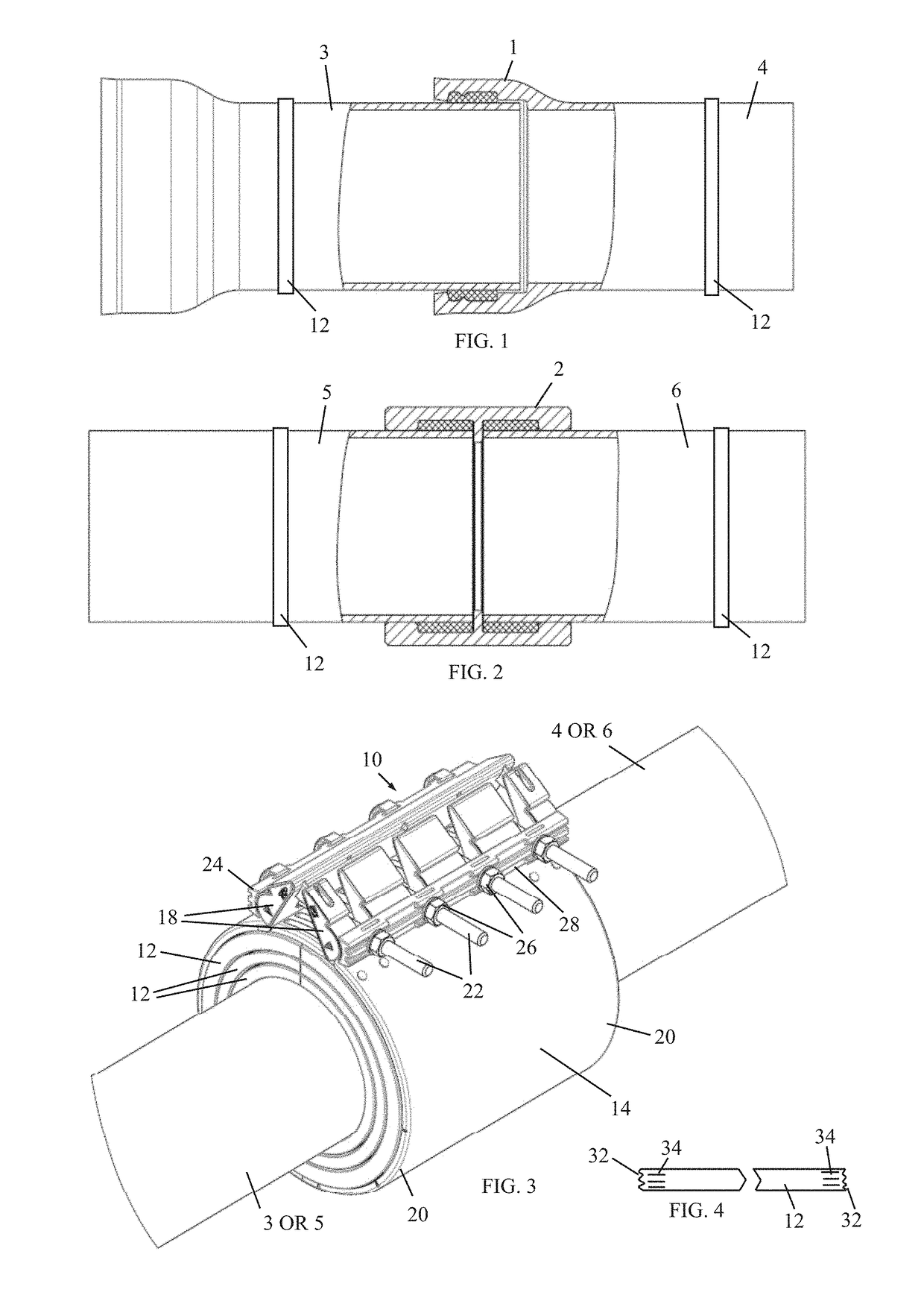
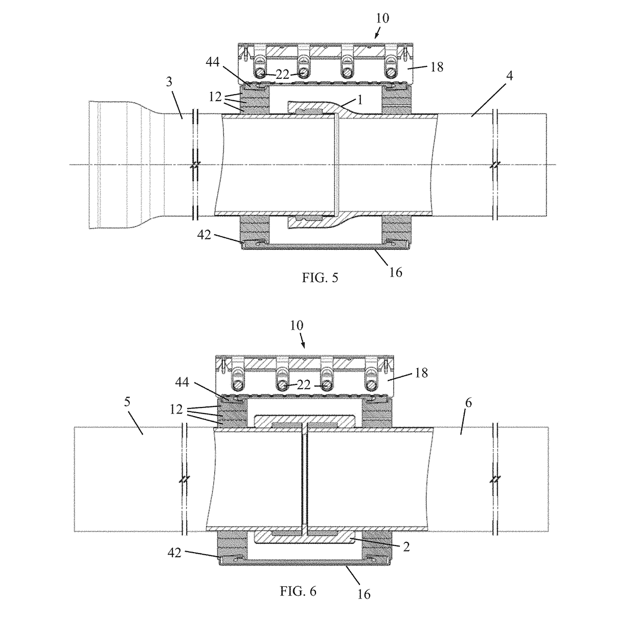
[0019]FIG. 1 illustrates a bell joint coupling 1, which has some leak. The bell joint coupling 1 is at the end of a pipe 4 and is connected to another pipe 3.

[0020]Similarly, FIG. 2 illustrates a sleeve joint coupling 2, which has some leak. The sleeve joint coupling 2 may be used to connect pipes 5 and 6.

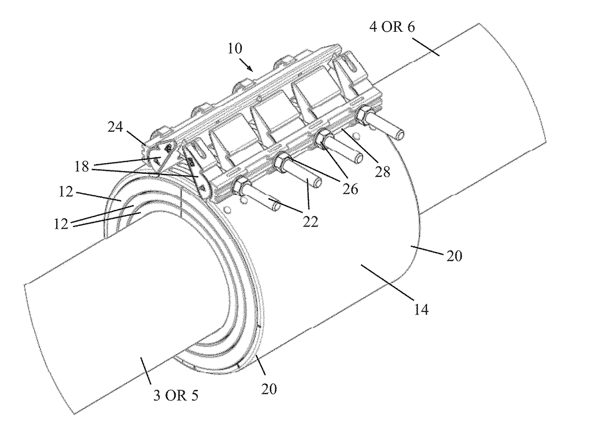
[0021]Reference is now made additionally to FIG. 3. In accordance with a non-limiting embodiment of the present invention, a pipe coupling encapsulation assembly 10 is provided to repair the leaking pipe joints, without having to interrupt flow through the pipes and joint couplings. The pipe coupling encapsulation assembly 10 includes two elastomeric partial rings 12, which may be made of natural or synthetic rubber or other suitable material. Each elastomeric partial ring 12 is wrapped or otherwise placed around one of the pipes on opposite sides of the leaking joint coupling (1 or 2), as shown in FIGS. 1 and 2.

[0022]If desired, each elastomeric partial ring 12 may be secured in p...


PUM


Abstract

A method for pipe coupling encapsulation includes placing two elastomeric partial rings around pipes on opposite sides of a leaking joint coupling, taking a repair coupling, which includes a band and opposing clamp members extending outwards from ends of the band, and placing the band around the leaking joint coupling such that opposite end portions of the band overlie the elastomeric partial rings, and tightening the opposing clamp members towards each other with one or more tightening elements.

Description


Claims


Application Information

Patent Timeline
IPC IPC(8): F16L55/172
CPCF16L55/172F16L55/178
Inventor CHIPROOT, AVI
Owner KRAUSZ IND
Why Eureka
Try Eureka