Charge and discharge control device

a control device and discharge technology, applied in the direction of charging stations, electric vehicle charging technology, transportation and packaging, etc., can solve the problems of secondary battery charging capacity deterioration under low-temperature environment, secondary battery not showing sufficient charge capacity, and battery temperature rise cannot be expected. , to achieve the effect of preventing the temperature rise of storage battery, and sufficient rise of storage battery temperatur

Active Publication Date: 2018-09-13
HONDA MOTOR CO LTD
View PDF10 Cites 16 Cited by
  • Summary
  • Abstract
  • Description
  • Claims
  • Application Information

AI Technical Summary

Benefits of technology

[0038]According to the configuration of (1), since the charging and discharging are alternately repeated between two storage batteries having the temperature equal to or lower than the threshold value, the self-heating value of the storage battery increases and the temperature of the storage battery sufficiently rises.
[0039]According to the configuration of (2), since the charging and discharging is stopped at the time when the temperature of at least one of the two storage batteries reaches a predetermined value or higher, it is possible to prevent the temperature rise of the storage battery more than require.
[0040]According to the configuration of (3), the temperature of the storage battery can rise while the state of charge of the two storage batteries is not changed at the time of stopping the charging / discharging between two storage batteries. Further, since the state of charge is not changed, there is no need to compensate for the discharge or recharge.
[0041]According to the configuration of (5), since the heat generated in the electric device accompanying with the charging and discharging of the storage battery is transferred to the storage battery via the temperature adjustment circuit, it is possible to raise the temperature of the storage battery by not only the self-heating of the storage battery but also the heat generated in the electric device.
[0042]According to the configuration of (6), since the temperature of the storage battery can be raised before charging the storage battery mounted in the transport vehicle or discharging the storage battery due to driving of the transport vehicle, it is possible to maximize the charge / discharge capacity of the storage battery.
[0043]According to the configuration of (7), it is possible to maximize the charge / discharge capacity of the storage battery by raising the temperature of the storage battery before the charging / discharging of the storage battery according to the electric power demand from the electric power system.

Problems solved by technology

For example, the charge capacity of a secondary battery deteriorates under a low-temperature environment.
Accordingly, even when a secondary battery in a low-temperature environment is charged, the secondary battery would not exhibit a sufficient charge capacity.
However, the temperature rise of the battery due to the self-heating is not so large, and the sufficient temperature rise of the battery cannot be expected.

Method used


Image

  • Charge and discharge control device
  • Charge and discharge control device
  • Charge and discharge control device

Examples


first embodiment

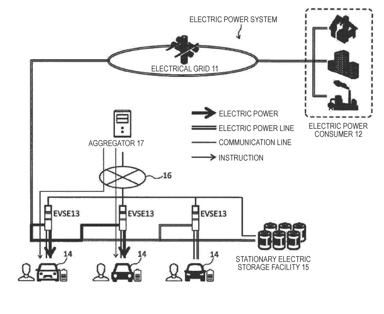
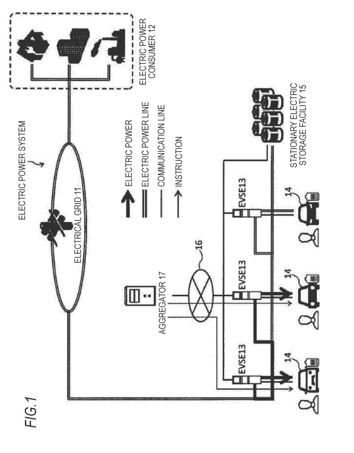
[0055]A Vehicle-to-Grid (V2G) system is a system which exchanges electric power between an electric power system including a commercial electrical grid and an electric vehicle and when the electric vehicle is not used as a transport means, a storage battery mounted in the electric vehicle is used as an electric power storage facility. Therefore, the electric power is bidirectionally exchanged between the electric vehicle participating in the V2G and the electric power system.

[0056]FIG. 1 is a diagram illustrating an entire configuration of the V2G system. As illustrated in FIG. 1, the V2G system includes an electric power system, an Electric Vehicle Service Equipment (EVSE) 13, an electric vehicle 14, a stationary electric storage facility 15, a communication network 16, and an aggregator 17. The electric power system includes an electrical grid 11 which transmits electric power generated by a power plant for generating electric power by energy of thermal power, wind power, atomic p...

second embodiment

[0079]FIG. 4 is a diagram illustrating a system including three electric vehicles and a stationary electric storage facility which are connected to EVSEs. The system illustrated in FIG. 4 includes an Electric Vehicle Service Equipment (EVSE) 23 which is an external power supply connected to an electrical grid 21 via a power distribution facility (not shown) or the like, an electric vehicle 24 such as Electric Vehicle (EV) or Plug-in Hybrid Electric Vehicle (PHEV) mounted with a chargeable / dischargeable storage battery, a stationary electric storage facility 25 in which a number of chargeable / dischargeable storage batteries are installed, and a communication network 26.

[0080]In the example illustrated in FIG. 4, the three electric vehicles 24 are connected to three EVSEs 23, respectively. The EVSE 23 and the stationary electric storage facility 25 are connected to each other via the communication network 26, so that instructions relating to charging and discharging of the storage bat...


PUM


Abstract

A charge and discharge control device includes a control unit which controls charging and discharging of a plurality of storage batteries capable of exchanging electric power via an external electrical grid; and an acquisition unit which acquires a temperature of each of the storage batteries. When there are at least two storage batteries having a temperature equal to or lower than a threshold value among the plurality of storage batteries, the control unit controls the two storage batteries to repeatedly perform charging and discharging in turn between the two storage batteries.

Description

CROSS-REFERENCE TO RELATED APPLICATIONS[0001]The present application claims the benefit of priority of Japanese Patent Application No. 2017-046584, filed on Mar. 10, 2017, the content of which is incorporated herein by reference.Technical Field[0002]The present invention relates to a charge and discharge control device for a plurality of storage batteries.Background Art[0003]A secondary battery has characteristics that a discharge capacity and a charge capacity thereof are dependent on a temperature. For example, the charge capacity of a secondary battery deteriorates under a low-temperature environment. Accordingly, even when a secondary battery in a low-temperature environment is charged, the secondary battery would not exhibit a sufficient charge capacity. In view of this characteristics, JP-A-2013-109859 discloses a battery control device which keeps a secondary battery warm.[0004]The battery control device described in JP-A-2013-109859 includes a plurality of charging / dischargi...

Claims


Application Information

Patent Timeline
Patent Type & Authority Applications(United States)
IPC IPC(8): H02J7/00
CPCH02J7/0013H02J7/0091B60L53/00H02J2310/48H02J3/322B60L53/63B60L53/65B60L53/53B60L53/67H02J7/342H02J7/007194Y02T10/70Y02T90/167Y02T90/12Y02T10/7072Y02T90/14Y04S30/14Y04S10/126Y02E60/00H02J7/04Y04S30/12
Inventor HOMMA, KEIICHIRO
Owner HONDA MOTOR CO LTD
Why Eureka
Try Eureka