AI technical title is built by Patsnap AI team. It summarizes the technical point description of the patent document.
a driving mechanism and inner component technology, applied in the direction of printers, cameras, instruments, etc., can solve the problem of how to achieve efficient space utilization of inner components within the driving mechanism, and become an important issu
Active Publication Date: 2018-11-22
TDK TAIWAN
View PDF12 Cites 21 Cited by
Summary
Abstract
Description
Claims
Application Information
AI Technical Summary
This helps you quickly interpret patents by identifying the three key elements:
Problems solved by technology
Method used
Benefits of technology
Benefits of technology
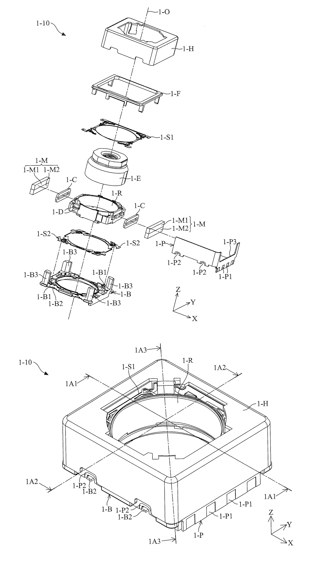
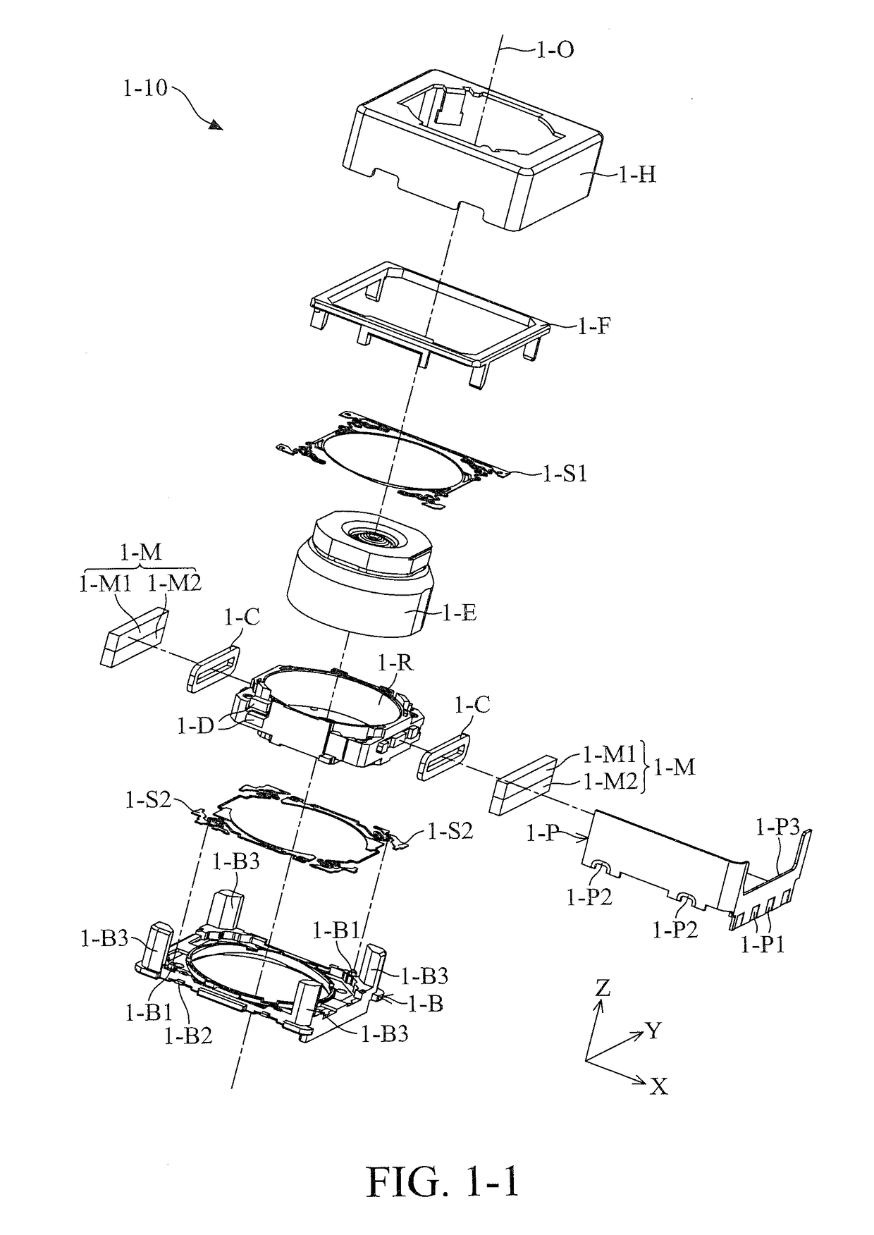
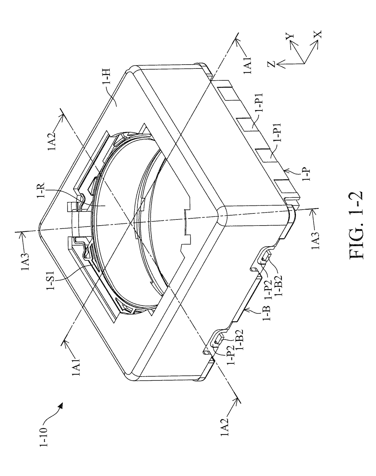
The present disclosure provides a driving mechanism for moving an optical element, which includes a housing, a fixed module, a holder, and a driving assembly. The driving assembly includes a driving module, a carrying base, and a damping member. The driving module is fixed to the housing and drives the holder and the optical element to move relative to the frame. The carrying base is disposed in the frame and includes a carrying body and first and second stop portions. The damping member is in direct contact with the positioning members and the carrying body. The driving mechanism also includes a driving module that includes a housing, a frame, a holder, and a driving assembly. The frame is fixed to the housing and includes a depressed surface adjacent to the housing. The holder is movably disposed in the housing for holding the optical element. The driving mechanism provides a solution for moving the optical element in a stable and efficient manner.
Problems solved by technology
However, owing to the miniaturization of the electronic devices, how to achieve efficient space utilization of the inner components within the driving mechanism has become an important issue.
Method used
Image
Click on the blue label to locate the original text in one second.
Reading with bidirectional positioning of images and text.
Examples
Embodiment Construction
[0162]The making and using of the embodiments of an electromagnetic driving system are discussed in detail below. It should be appreciated, however, that the embodiments provide many applicable inventive concepts that can be embodied in a wide variety of specific contexts. The specific embodiments discussed are merely illustrative of specific ways to make and use the embodiments, and do not limit the scope of the disclosure.
[0163]Unless defined otherwise, all technical and scientific terms used herein have the same meaning as commonly understood by one of ordinary skill in the art to which this disclosure belongs. It should be appreciated that each term, which is defined in a commonly used dictionary, should be interpreted as having a meaning conforming to the relative skills and the background or the context of the present disclosure, and should not be interpreted in an idealized or overly formal manner unless defined otherwise.
[0164]In the following detailed description of the pre...
PUM
Abstract
A driving mechanism for supporting an optical member is provided, including a base, a frame, a movable portion, a driving module, and an adhesive member. The base includes a plurality of first sidewalls, and at least one recess is formed on the first sidewalls. The frame includes a plurality of second sidewalls, and at least one opening is formed on the second sidewalls. The base and the frame form a hollow box, and the opening corresponds to the recess. The movable portion and the driving module are disposed in the hollow box. The driving module can drive the movable portion to move relative to the base. The adhesive member is accommodated in the opening and the recess, and extended along the first sidewalls. The adhesive member is disposed between the first sidewalls and the second sidewalls.
Description
CROSS REFERENCE TO RELATED APPLICATIONS[0001]The present application claims priority to U.S. Provisional Patent Application No. 62 / 507,478, filed on May 17, 2017, and China Patent Application No. 201810443890.1 filed on May 10, 2018, which is incorporated by reference herein in its entirety.BACKGROUND OF THE DISCLOSUREField of the Disclosure[0002]The disclosure relates to a driving mechanism, and more particularly to a driving mechanism for moving an optical element.Description of the Related Art[0003]As technology has advanced, a lot of electronic devices (for example, cameras and smartphones) have incorporated the functionality of taking photographs and recording video. These electronic devices have become more commonplace, and have been developed to be more convenient and thin. In some electronic devices, an electromagnetic driving mechanism such as a Voice Coil Motor (VCM) is disposed therein to adjust the focus of a lens. However, owing to the miniaturization of the electronic ...
Claims
Application Information
Patent Timeline
Application Date:The date an application was filed.
Publication Date:The date a patent or application was officially published.
First Publication Date:The earliest publication date of a patent with the same application number.
Issue Date:Publication date of the patent grant document.
PCT Entry Date:The Entry date of PCT National Phase.
Estimated Expiry Date:The statutory expiry date of a patent right according to the Patent Law, and it is the longest term of protection that the patent right can achieve without the termination of the patent right due to other reasons(Term extension factor has been taken into account ).
Invalid Date:Actual expiry date is based on effective date or publication date of legal transaction data of invalid patent.
Patent Type & AuthorityApplications(United States)

