Eureka AIR delivers breakthrough ideas for toughest innovation challenges, trusted by R&D personnel around the world.

Air intake device for internal combustion engine

a technology for internal combustion engines and air intake devices, which is applied in the direction of combustion-air/fuel-air treatment, valve housings, machines/engines, etc., can solve the problems of low gas flow, tumble flow and swirl flow, and achieve the effect of suppressing the gas flow

Active Publication Date: 2018-12-06
NISSAN MOTOR CO LTD
View PDF0 Cites 8 Cited by
  • Summary
  • Abstract
  • Description
  • Claims
  • Application Information

AI Technical Summary

Benefits of technology

The present invention ensures that the water discharge passage is separate from the main intake air passage, which prevents the intake air from being obstructed when the valve is closed. This prevents a decrease in the gas flow.

Problems solved by technology

However, in the above water discharge structure, even when the valve is closed, a gap appears between the control valve and the housing bottom wall caused by the water collection groove, and gas flow (for example, tumble flow and swirl flow) becomes low due to air leak from this gap.

Method used


Image

  • Air intake device for internal combustion engine
  • Air intake device for internal combustion engine
  • Air intake device for internal combustion engine

Examples


Embodiment Construction

[0015]In the following, an embodiment of the present invention will be explained with reference to the drawings.

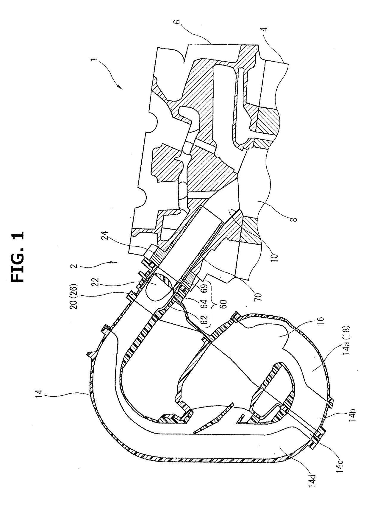
[0016]FIG. 1 schematically shows an air intake device 2 for an internal combustion engine 1 according to the present invention. In the present embodiment, an example in which air intake device 2 of the present invention is applied to inline four cylinder internal combustion engine 1 is shown, and internal combustion engine 1 includes a cylinder block 4 and a cylinder head 6 disposed on cylinder block 4. Cylinder head 6 includes air intake ports 10 which introduce intake air to combustion chambers 8. Air intake ports 10 are provided to respective cylinders, and the downstream side part of each of intake ports 10 which is close to each of combustion chambers 8 is branched into two.

[0017]An intake manifold 4 attached to cylinder head 6 is formed by joining four members 14a to 14d made of hard synthetic resin to each other by vibration welding. Intake manifold 4 includes a col...


PUM

PropertyMeasurementUnit
cylindrical shapeaaaaaaaaaa
areaaaaaaaaaaa
lengthaaaaaaaaaa

Abstract

An air intake device for an internal combustion engine of the present invention includes a water discharge passage extending from a bottom surface of a control valve housing part recessed in a housing passage forming part of an air intake passage to an air intake port. The water discharge passage is formed independently from the air intake passage, and includes: a water collection groove recessed in the bottom surface; a water discharge hole formed penetrating a cover of a valve control housing; and a water discharge hole penetrating a flange part of an insert inserted into the air intake port. The downstream end of the water discharge hole is connected to a space defined between an air intake port inner wall surface and an insert cylindrical part.

Description

TECHNICAL FIELD[0001]The present invention relates to an air intake device for an internal combustion engine.BACKGROUND TECHNOLOGY[0002]An air intake device has been known in which gas flow is formed in a combustion chamber of an internal combustion engine by controlling the opening area of an air intake passage of an intake manifold. This type of the air intake device has been used in cold districts, and measures to discharge moisture content from around a control valve has been taken so as to suppress that moisture content in intake air flowing to the air intake device adheres to a rotation shaft of the control valve and it is frozen.[0003]For example, in a patent document 1, a water collection groove is provided on the bottom wall of a housing to suppress the intrusion of moisture content into the gap between the rotation shaft of a control valve and a bearing. Both of the end parts of this water collection groove are inclined such that the center part of the housing bottom wall ...

Claims


Application Information

Patent Timeline
Patent Type & Authority Applications(United States)
IPC IPC(8): F02M35/10F02F1/42F02B31/06F02D9/10F16K27/02
CPCF02M35/10255F02M35/10085F02F1/4257F02B31/06F02D9/10F02M35/10262F16K27/0227F02M35/104F02M35/10F02M35/10268F02M35/10321F02M35/10354F02D9/103F02D9/1095F16K27/065F16K27/003Y02T10/12F02M35/10209F02F1/42
Inventor OOKI, OSAMUIIJIMA, KAZUKI
Owner NISSAN MOTOR CO LTD
Why Eureka
Eureka Blog
Learn More