
Table

a technology for tables and tables, applied in the field of structures, can solve the problems of tabletops constructed from wood, particleboard or metal, table tops that are awkward or difficult to move, and tabletops constructed from wood or metal are also relatively expensiv

Active Publication Date: 2020-07-09
LIFETIME PRODUCTS
View PDF2 Cites 10 Cited by
  • Summary
  • Abstract
  • Description
  • Claims
  • Application Information

AI Technical Summary

Benefits of technology

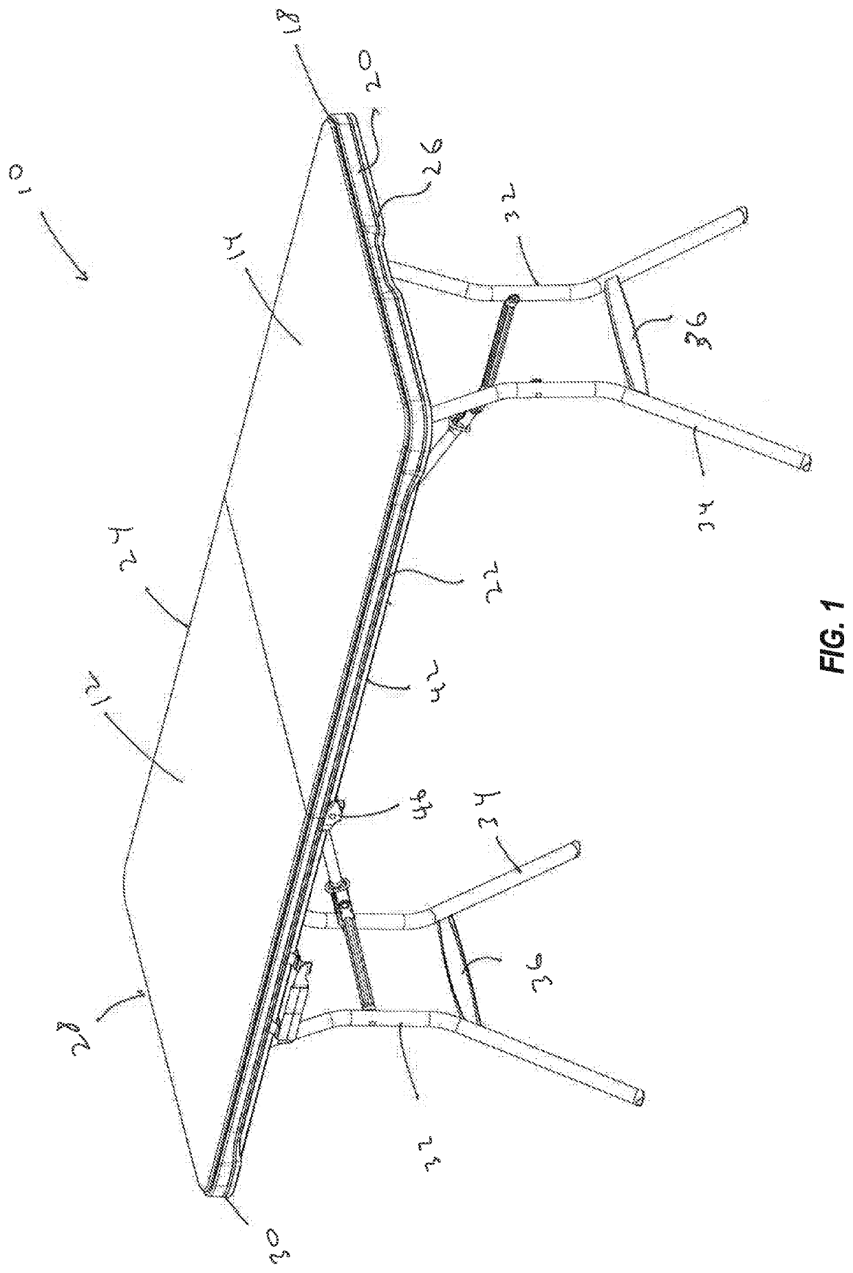
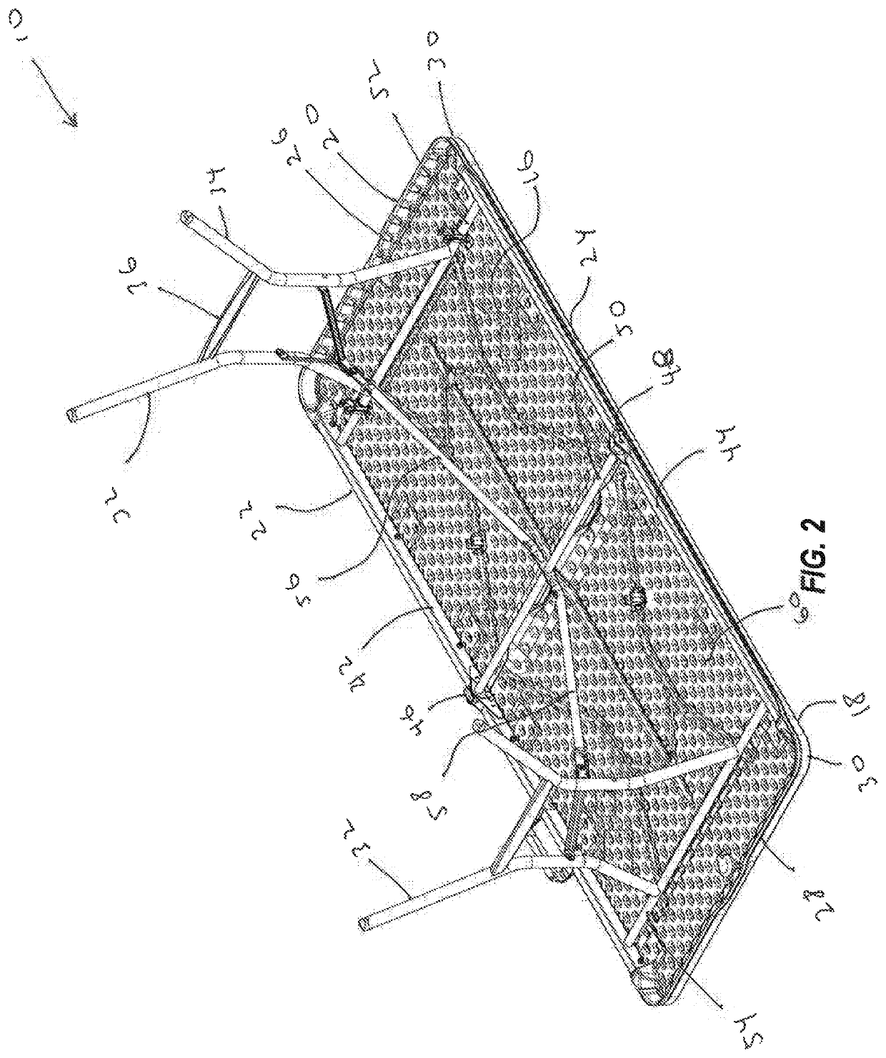
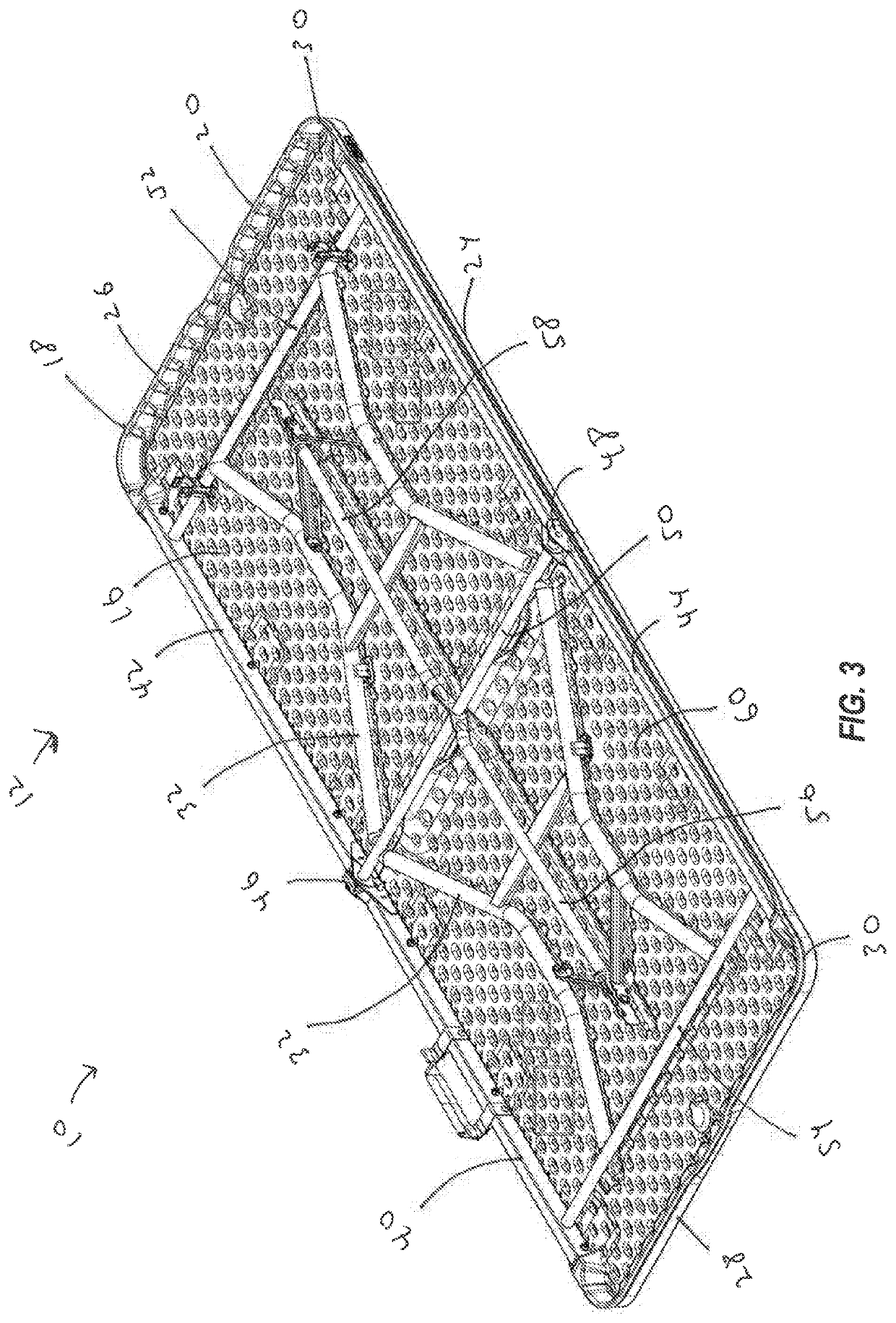
This patent describes a molded plastic table with an improved lip design. The lip has one or more inwardly extending portions that increase its strength and rigidity. The lip may also have channels or recesses that allow for gas flow during the molding process. The table also includes a frame that includes side rails and a receiving portion that receives the inwardly extending portions of the lip. This design creates a table with high strength, impact resistance, and aesthetic appeal. The lip may hide the frame or allow for a portion of the frame to be visible during use of the table.

Problems solved by technology

Tabletops constructed from wood, particleboard or metal, however, are often relatively heavy and this may make the table awkward or difficult to move.
Tabletops constructed from wood or metal are also relatively expensive and these types of tabletops must generally be treated or finished before use.
In addition, because these wooden and metal tabletops are relatively heavy, the cost of shipping and transportation of the tables may be increased.
The weight of the tabletop may make the tables more difficult to move and store.
Disadvantageously, tabletops constructed from lightweight materials may require large reinforcing members or other structural parts such as braces, brackets, support members and the like to strengthen the tabletop.
While these additional parts may increase the strength of the tabletop, the added parts may also increase the weight of the table.
These additional parts may result in increased manufacturing costs and require additional time to assemble the table.
In addition, extra fasteners may be required to assemble and connect these parts to the table, which may require extra time and labor during the manufacturing process.
The additional parts and fasteners may further increase the cost of the table and make the table more difficult to manufacture.
Moreover, these additional parts and fasteners may have sharp edges that can injure a user's legs or arms.

Method used


Image

  • Table
  • Table
  • Table

Examples


Embodiment Construction

[0036]The following exemplary embodiments are generally described in connection with tables. The principles of the present invention, however, are not limited to tables. In particular, the principles of the present invention may be implemented in connection with other articles of furniture and in other structures that include molded plastic components. In addition, it will be understood that, with the benefit of the present disclosure, the tables disclosed herein can have a variety of shapes, sizes, configurations, and arrangements. Moreover, while the tables shown in the accompanying figures may be configured for use in connection with fold-in-half tables, it will be appreciated the tables may have any suitable shapes, sizes, configurations, and / or arrangements. For instance, the tables described herein may be utility tables, round tables, personal tables, conference tables, seminar tables, recreation tables, adjustable height tables, card tables, and the like. Further, the inventi...


PUM

PropertyMeasurementUnit
plasticaaaaaaaaaa
plastic structureaaaaaaaaaa
heightaaaaaaaaaa

Abstract

A molded plastic structure may comprise a tabletop with an upper surface and a lower surface. A lip may extend downwardly relative to the lower surface of the tabletop, and the lip may include an outer surface and an inner surface. An inwardly extending portion may extend inwardly from the inner surface of the lip. A frame may be connected to the table top and the frame may include a side rail of a frame. The side rail may include a receiving portion that receives the inwardly extending portion. The side rail may also include a portion that supports the lower surface of the table top and a portion that supports the lip.

Description

BACKGROUNDField of the Invention[0001]The present invention generally relates to structures including at least a portion constructed from plastic and, more particularly, to furniture, such as tables, that may include molded plastic components.Description of Related Art[0002]Many different types of tables are known and are used for a variety of purposes. For example, conventional tables may include legs that are pivotally attached to a tabletop and the legs may be movable between a use position in which the legs extend outwardly from the tabletop and a storage position in which the legs are folded against the tabletop. Conventional tables with relatively large tabletops and folding legs are often referred to as “banquet tables” and these tables are frequently used in assembly halls, banquet halls, convention centers, hotels, schools, churches, and other locations where large groups of people meet. These tables can often be positioned in an assortment of configurations and used in a v...

Claims


Application Information

Patent Timeline
Patent Type & Authority Applications(United States)
IPC IPC(8): A47B13/08A47B3/087A47B13/00
CPCA47B2013/085A47B13/083A47B3/087A47B13/003A47B3/0912B29C49/42B29C49/00B29C49/0005A47B3/00
Inventor JOHNSON, MITCHBOYDSTON, KEVIN
Owner LIFETIME PRODUCTS
Learn More