Reducing agent injection device and exhaust gas treatment method

Active Publication Date: 2017-10-05
NGK INSULATORS LTD
View PDF10 Cites 10 Cited by
  • Summary
  • Abstract
  • Description
  • Claims
  • Application Information

AI Technical Summary

Benefits of technology

[0017]According to the reducing agent injection device of the present invention, the urea water solution sprayed by the urea spraying device is supplied into the cell of the honeycomb structure. Then, the urea in the urea water solution is heated and hydrolyzed in the electrically heated honeycomb structure to generate ammonia, and the generated ammonia is injected. A carrier gas inlet that introduces carrier gas is provided between the urea spr

Problems solved by technology

However, when urea is added to an electrically heated honeycomb structure (honeycomb heater), the temperature of a portion to which urea is added is lowered, and temperature unevenness in the honeycomb heater occurs.
When urea deposit is generated, the path of the honeycomb heater is cut, and decomposition of urea to NH3 is

Method used


Image

  • Reducing agent injection device and exhaust gas treatment method
  • Reducing agent injection device and exhaust gas treatment method
  • Reducing agent injection device and exhaust gas treatment method

Examples


examples

[0115]The following describes the present invention more specifically with examples, but the present invention is not limited to these examples.

examples 1 to 19

, Comparative Examples 1 to 8

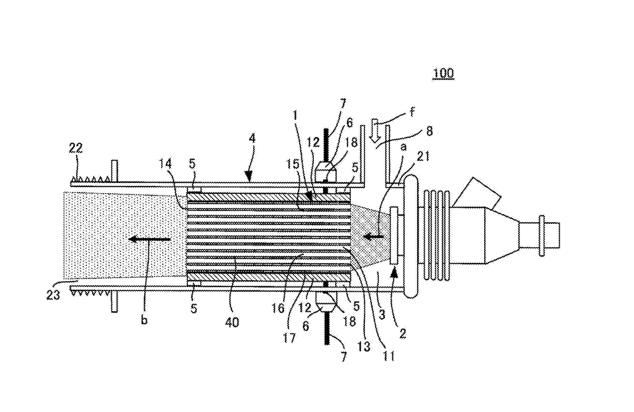
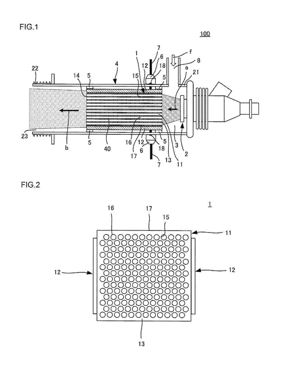
[0116]A reducing agent injection device as shown in FIG. 1 was manufactured. It is specifically described as follows. First, a honeycomb structure 1 was prepared. It is specifically described hereinbelow.

[0117]The silicon carbide (SiC) powder and metal silicon (Si) powder were mixed in a mass ratio of 70:30 to prepare a ceramic raw material. Then, hydroxypropyl methyl cellulose as a binder and a water absorbable resin as a pore former were added to the ceramic raw material, and water was added together to prepare a forming raw material. Then, the forming raw material was kneaded by a vacuum pugmill to form a round pillar-shaped kneaded material. The content of the binder was 7 parts by mass when the ceramic raw material was 100 parts by mass. The content of the pore former was 3 parts by mass when the ceramic raw material was 100 parts by mass. The content of water was 42 parts by mass when the ceramic raw material was 100 parts by mass. The average part...


PUM

PropertyMeasurementUnit
Temperatureaaaaaaaaaa

Abstract

A reducing agent injection device includes a honeycomb structure and a urea spraying device spraying a urea water solution in mist form. In addition, the reducing agent injection device includes a carrier gas inlet that introduces carrier gas f between the urea spraying device and the honeycomb structure. The exhaust gas treatment method of the present invention supplies the urea water solution from the urea spraying device into the cells from the first end face of the honeycomb structure body to generate the ammonia, while introducing the carrier gas f from the carrier gas inlet, and injecting the ammonia to the outside to treat exhaust gas containing NOX.

Description

[0001]The present application is an application based on JP-2016-068908 filed on Mar. 30, 2016 with Japan Patent Office, the entire contents of which are incorporated herein by reference.BACKGROUND OF THE INVENTIONField of the Invention[0002]The present invention relates to a reducing agent injection device for purifying exhaust gas, and an exhaust gas treatment method.Description of the Related Art[0003]Conventionally, a selective catalytic reduction type NOX catalyst (an SCR catalyst) has been used to purify nitrogen oxides (NOX) in the exhaust gas discharged from various kinds of engines and the like (for example, see Patent Document 1).[0004]The exhaust gas purifying device described in Patent Document 1 has a catalyst (an SCR catalyst) mounted on an exhaust pipe of an engine and means for injecting urea water into the exhaust pipe between the engine and the catalyst. Moreover, a plurality of urea water injection means, which mixes the urea water and the exhaust gas, and mixes t...

Claims


Application Information

Patent Timeline
IPC IPC(8): F01N3/20B01D53/90F01N3/28B01D53/94
CPCF01N3/2066B01D53/9418B01D53/9431B01D53/90F01N3/2842F01N3/2026F01N2610/02B01D2251/2067B01D2255/50B01D2255/20723B01D2255/2092B01D2255/808B01D2257/404B01D2251/2062B01D53/56B05B7/0416B05B17/04B05B17/06B01D2258/01B01D2259/124B01D53/944F01N2610/102F01N2610/1453Y02T10/12
Inventor SAIKI, KATSUMIOMIYA, YOSHIMASAISHIHARA, TAKUYA
Owner NGK INSULATORS LTD
Why Eureka
Try Eureka