Apparatus, method, and system for precise LED lighting

Active Publication Date: 2018-12-06
MUSCO
View PDF6 Cites 8 Cited by
  • Summary
  • Abstract
  • Description
  • Claims
  • Application Information

AI Technical Summary

Benefits of technology

The envisioned LED lighting system improves precision lighting by using a multi-part visoring system for sharper and stiffer cutoff, and a multi-part differential reflection system for better intensity distribution at or near beam pattern edges and across the beam pattern. This system can be tailored to different fixtures for different applications without replacing the entire optic system or designing a new fixture, and it avoids striations at the edge of beam patterns.

Problems solved by technology

However, even within demanding lighting applications like sports and roadway there are still areas having needs unmet or under-met; irregular racetracks and five-pole baseball layouts are two possible examples.
In these niche areas of what is referred to as high demand lighting applications circumstances align (e.g., long setbacks with shallow seating, flat tracks, roofless vehicles) such that conventional lighting is inadequate—cutoff is not sharp enough, the beam is not smooth enough, etc.—even when using some of the more advanced lighting technologies discussed in U.S. Pat. Nos. 5,887,969 and 8,789,967.
Merely adding additional lenses, visors, baffles, light absorbing material, etc. to a lighting fixture using conventional materials and conventional means—as is standard practice in the industry—does not adequately address the lighting needs of high demand lighting applications; conventional wisdom adds weight and cost, reduces transmission efficiency and light that is useful for the application, and still cannot provide the needed beam control.

Method used


Image

  • Apparatus, method, and system for precise LED lighting
  • Apparatus, method, and system for precise LED lighting
  • Apparatus, method, and system for precise LED lighting

Examples


exemplary embodiment 1

B. Exemplary Embodiment 1

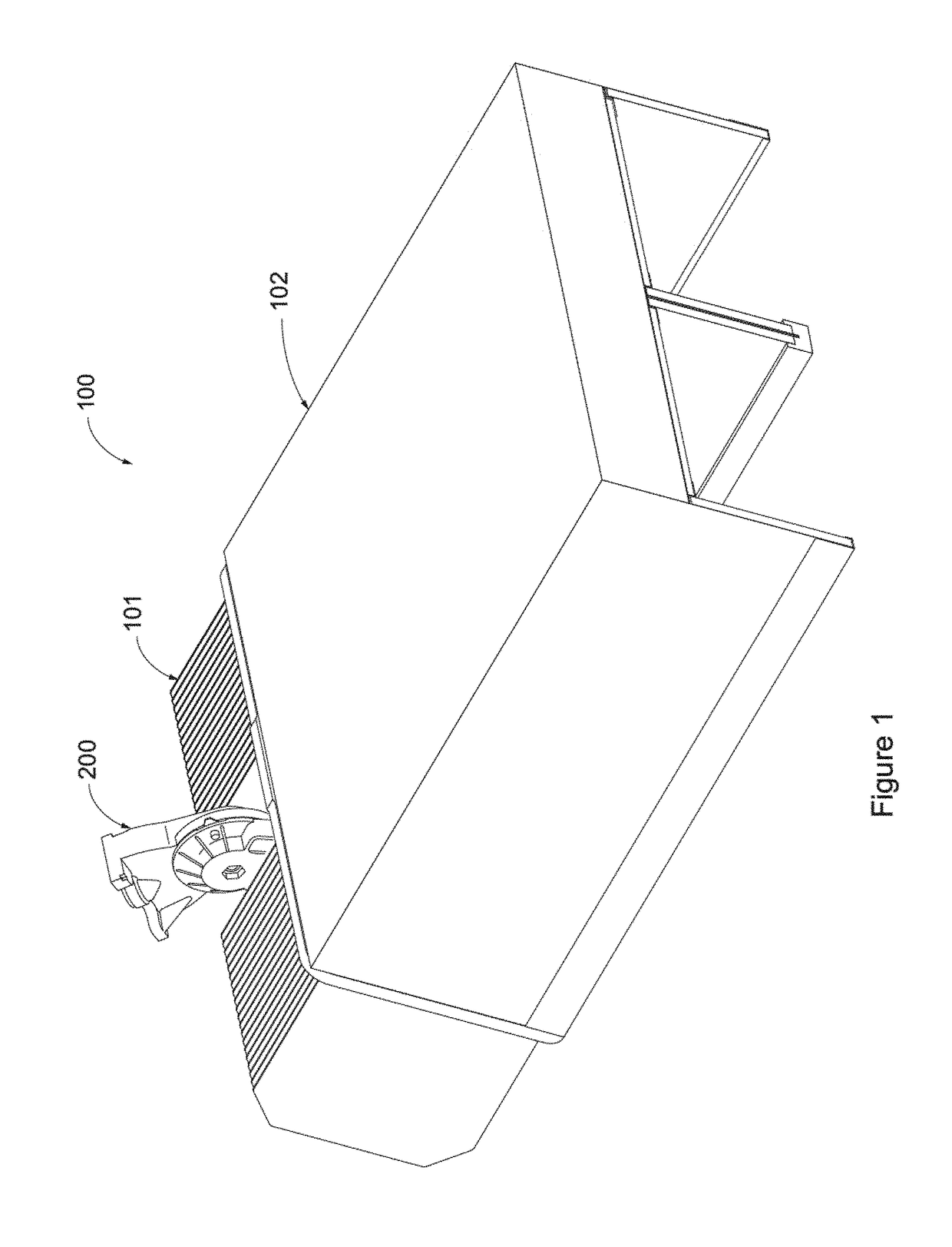
[0058]FIGS. 1-10 illustrate a first embodiment which may be best suited for difficult lighting applications such as the aforementioned irregular racetracks; though this is by way of example and not by way of limitation. Generally speaking, fixture 100 comprises an external light redirecting portion 102 which includes aspects of the multi-part differential reflection and / or multi-part visoring systems, a housing with internal components 101 which includes aspects of the multi-part optic system, and an adjustable armature 200 for affixing such to a crossarm, pole, or other elevating structure (not illustrated); adjustable armature 200 may be similar in design to that described in aforementioned U.S. patent application Ser. No. 12 / 910,443, or otherwise.

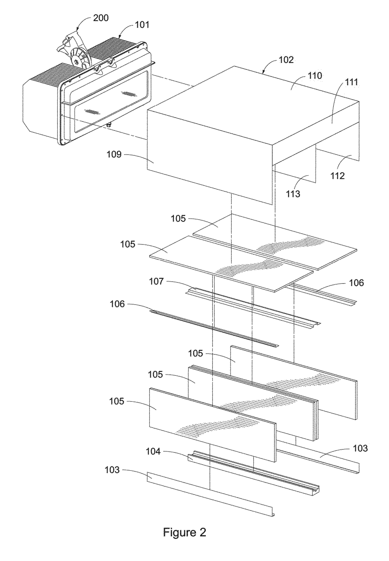
[0059]FIG. 2 illustrates in greater detail components of external light redirection portion 102. A generally rigid housing having a exterior top 110 and exterior sides 109 support one or more pieces of glass or o...

exemplary embodiment 2

C. Exemplary Embodiment 2

[0062]In some situations, there is adequate fixture setback to permit locating the second portion of the multi-part visoring system remote from the first portion; the benefit to doing so is reducing the amount of light which must be absorbed to provide the sharp cutoff, thereby reducing light loss and preserving fixture efficiency. In this alternative embodiment (see FIGS. 11 and 12) said second visor portion 111 is located some distance away from the rest of fixture 100 (e.g., several feet) and mounted to a base 204 by bolting 205 or otherwise affixing a bracket 206 to a post or other elevating structure 203 which is integral to or affixed to base 204, said bracket 206 adapted to grip and provide rigidity to second visor portion 111.

exemplary embodiment 3

D. Exemplary Embodiment 3

[0063]In some situations, the lighting fixture is elevated significantly higher than the target area (e.g., dozens of feet) and so more severe aiming angles are needed to adequately illuminate the target area—as in five-pole baseball layouts. As such, an alternative embodiment for such a purpose (though not limited to such) is illustrated in FIGS. 14-22. According to the present embodiment the same housing with internal components 101 and adjustable armature 200 (not illustrated) is used as in Embodiments 1 and 2; however, external light redirection portion 1001 actually includes a third visor portion. Similar to principles discussed in U.S. Patent Publication No. 2013 / 0250556 incorporated by reference herein in its entirety, if desired the multi-part visoring system may include a first fixed reflective visor portion 1010, a first adjustable reflective visor portion 1009, and aforementioned second light absorbing portion 111. First fixed visor portion 1010 a...


PUM


Abstract

Lighting applications which are particularly difficult to light because of “non-standard” target area characteristics or the like would benefit from advancements in lighting design. That being said, conventional wisdom in lighting design has reached a point of diminishing returns in terms of beam control. Envisioned is an LED lighting system designed for precision lighting insomuch that—as compared to state-of-the-art LED lighting fixtures—sharpness of cutoff is improved while in at least some cases simultaneously allowing a steeper cutoff without undesirable beam shift. Furthermore, overall beam dimensions can be tailored fixture-to-fixture for an application without replacing an entire optic system or designing an entirely new fixture, and control of intensity distribution is improved (e.g., by avoiding striations at the edge of beam patterns). Said envisioned LED lighting system employs a number of materials not used in conventional LED lighting systems in novel ways to achieve the aforementioned.

Description

CROSS-REFERENCE TO RELATED APPLICATIONS[0001]This application claims priority under 35 U.S.C. §119 to provisional U.S. application Ser. No. 62 / 515,832, filed Jun. 6th, 2017, hereby incorporated by reference in its entirety.I. TECHNICAL FIELD OF THE INVENTION[0002]The present invention generally relates to improvements in LED lighting system design to provide more precise beam control in one or more planes. More specifically, the present invention relates to providing sharper cutoff, greater flexibility in providing tailored beam dimensions, and better control of intensity distribution as compared to state-of-the-art LED lighting fixtures through improved design of light directing (e.g., lens) and / or light redirecting (e.g., reflector) devices in multi-part components.II. BACKGROUND OF THE INVENTION[0003]Within the art of lighting design there are certain applications which are known to be much more demanding than others; for example, sports and roadway. These more demanding applicat...

Claims


Application Information

Patent Timeline
IPC IPC(8): F21V14/04F21V17/02F21K9/65F21K9/68
CPCF21V14/04F21V17/02F21K9/65F21K9/68F21S8/086F21V5/007F21V7/05F21V14/08F21W2131/103F21W2131/105F21Y2105/16F21Y2115/10F21V11/183
Inventor GORDIN, MYRONMCKEE, LUKE C.LICKISS, CHRIS P.
Owner MUSCO
Why Eureka
Try Eureka