
Directional Surface Marking Safety and Guidance Devices and Systems

a technology of safety and guidance devices and directional surfaces, applied in the direction of traffic signals, applications, roads, etc., can solve the problems of pedestrian aggravation, difficult to determine which direction is the department and which is the exit, and many pedestrian pathways, so as to reduce the incidence of wrong way driving, the effect of affordable and usabl

Active Publication Date: 2018-12-13
DRISKELL HLDG
View PDF4 Cites 2 Cited by
  • Summary
  • Abstract
  • Description
  • Claims
  • Application Information

AI Technical Summary

Benefits of technology

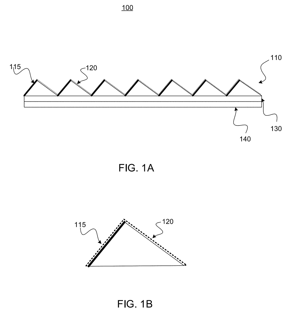
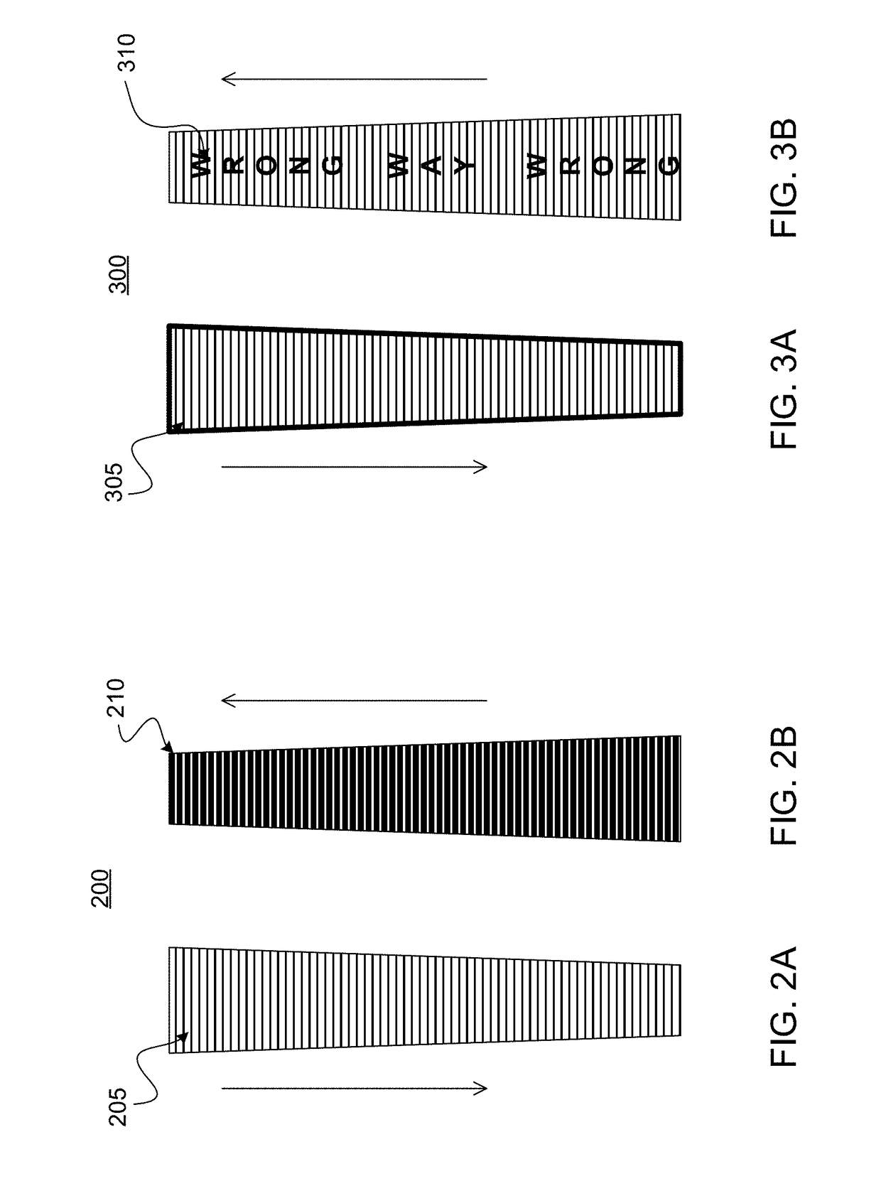
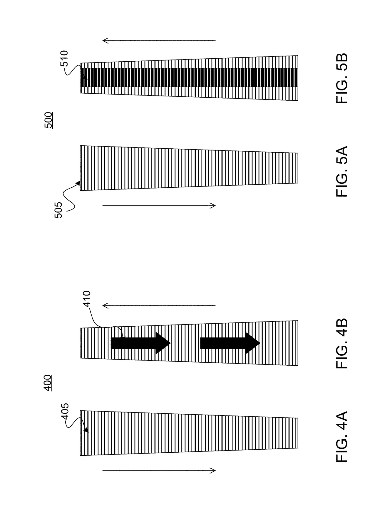
The present invention provides a system and devices to alert motorists, viewers, or users with a clear, concise message or alert that is easily visible and recognizable. The unique driving and viewing habits of these users are considered when providing the alert to reduce wrong way driving incidents on roadways and bicycle paths. The directional surface marking comprises different colors, text, or symbols that users may view depending on their direction of travel on a base surface. Additionally, the invention may also reduce wrong way cycling incidences on bicycle paths and lanes. The installation and use of bicycle paths and lanes are increasing worldwide, and they need alert of incorrect direction travel without significant wheel deflection of the cycle.

Problems solved by technology

Many pedestrian pathways, as in public parks and hallways of large public buildings such as hospitals, can be very complex and confusing to the traveling pedestrians.
However, it is difficult to determine which direction is the department and which is the exit.
These methods not only cause the pedestrian aggravation, but present a danger when emergency exiting is necessary.
Standard white markings are used and no pavement markers are used due to bicycle wheel deflection issues.
Bicycle paths can be dangerous in incorrect direction travel as well with the excessive roadway cycling speeds and limited bodily protection.

Method used


Image

  • Directional Surface Marking Safety and Guidance Devices and Systems
  • Directional Surface Marking Safety and Guidance Devices and Systems
  • Directional Surface Marking Safety and Guidance Devices and Systems

Examples


Embodiment Construction

[0053]The present disclosure provides generally for an improved marking system. More specifically, the present disclosure relates to directional surface markings that may provide directional messaging.

[0054]In the following sections, detailed descriptions of examples and methods of the disclosure will be given. The description of both preferred and alternative examples, though thorough, are exemplary only, and it is understood to those skilled in the art that variations, modifications, and alterations may be apparent. It is therefore to be understood that the examples do not limit the broadness of the aspects of the underlying disclosure as defined by the claims.

Glossary

[0055]User: as used herein refers to an individual who may interact with directional surface markings. In some embodiments, a user may comprise a pedestrian, cyclist, motorist, or passenger, as non-limiting examples.[0056]Directional Surface Markings: as used herein refers to a system or device that may provide direc...


PUM

PropertyMeasurementUnit
degree anglesaaaaaaaaaa
lengthaaaaaaaaaa

Abstract

In some embodiments, a directional surface marking maythat provides directional messaging to users based on their direction of travel on a base surface, such as a roadway, walkway, or interior flooring, as non-limiting examples. In some aspects, the directional messaging may comprise different colors, text, or symbols, wherein a user may view different directional messaging on a directional surface marking dependent on direction of travel. In some embodiments, directional surface markings may comprise a profile layer, wherein the profile layer may comprise a plurality of profiles, which may allow for an application of directional messaging.

Description

CROSS-REFERENCE TO RELATED APPLICATION[0001]This application claims priority to and the full benefit of U.S. Provisional Patent Application Ser. No. 62 / 518,112 (filed Jun. 12, 2017, and titled “DUAL COLOR ROAD MARKER SAFETY DEVICE”), the entire contents of which are incorporated herein by reference.BACKGROUND OF THE DISCLOSURE[0002]Since the inception of automobiles, motorists have caused or experienced automobile accidents. Head-to-head collisions are some of the most deadly accident types. These accidents most commonly occur when a motorist enters into a divided highway or a one way roadway in the incorrect direction. These accidents are disproportionally caused by impaired or aged motorists. As a result, there is a great need to alert motorists who unintentionally travel in the incorrect direction.[0003]Motorists, cyclists, and pedestrians utilize various infrastructure elements, such as signs, markings, and markers, to guide them down a road, lane, path, or hallway. One of the m...

Claims


Application Information

Patent Timeline
Patent Type & Authority Applications(United States)
IPC IPC(8): E01F9/529E01F9/524B29C39/02B29C43/24B29C37/00B32B3/30B32B7/12
CPCE01F9/529E01F9/524B29C39/02B29C43/24B29C37/0025B32B3/30B32B7/12B29L2031/7232B32B2590/00B32B2307/416B29K2995/003E01F9/50B29C59/046B29C43/222B29C43/52
Inventor DRISKELL, GREGORY W.GREEN, MICHAEL D.
Owner DRISKELL HLDG
Learn More