Cigar tube

a technology for cigars and receiving tubes, which is applied in the field of cigars, can solve the problems of user clothing becoming permeated with smoke odor, the type of device cannot be easily carried in the pocket of a user, and the complexity of the above-mentioned devices, etc., and achieves the effect of cost saving and convenient us

Active Publication Date: 2018-12-20
THINGYMAJIGGY LLC
View PDF10 Cites 6 Cited by
  • Summary
  • Abstract
  • Description
  • Claims
  • Application Information

AI Technical Summary

Benefits of technology

[0028]In yet another preferred embodiment, there is provided a cigar tube for receiving, slicing, and storing smoking articles such as, for instance a cigar and cigar filling tobacco, comprising a tubular member having a top end opposite a bottom end, where the top end defines an opening to an inner cavity that is adapted to receive and contain the cigar and cigar filling tobacco when inserted therein by a user. Such embodiments provide for the removal and disposal of ashes and / or tobacco strands from smoking articles such as a cigar, in a clean and efficient manner. Through various embodiments disclosed herein, the cigar tube also provides for product packaging for smoking articles, such as, for instance, cigars, rolling papers, cigar wraps, hemp-based rolling papers, pre-rolled cones, tobacco strands, marijuana (including medical grade marijuana), and / or cannabis (including medical grade cannabis).
[0033]In yet another embodiment, the invention describes a rolling paper container for the containment and dispensing of smoking articles, such as, for instance for rolling papers. Embodiments of the present invention make it possible to present the rolling papers more easily to the user.

Problems solved by technology

Such aforementioned devices are complex and do not provide for or accommodate advantages of the present invention.
This device differs from the other devices in that it is not intended to be used as a cigar extinguisher.
As a result, this type of device could not easily be carried in a pocket of a user.
Further, the user's clothing will become permeated with the smoke odor.

Method used


Image

  • Cigar tube
  • Cigar tube
  • Cigar tube

Examples


Embodiment Construction

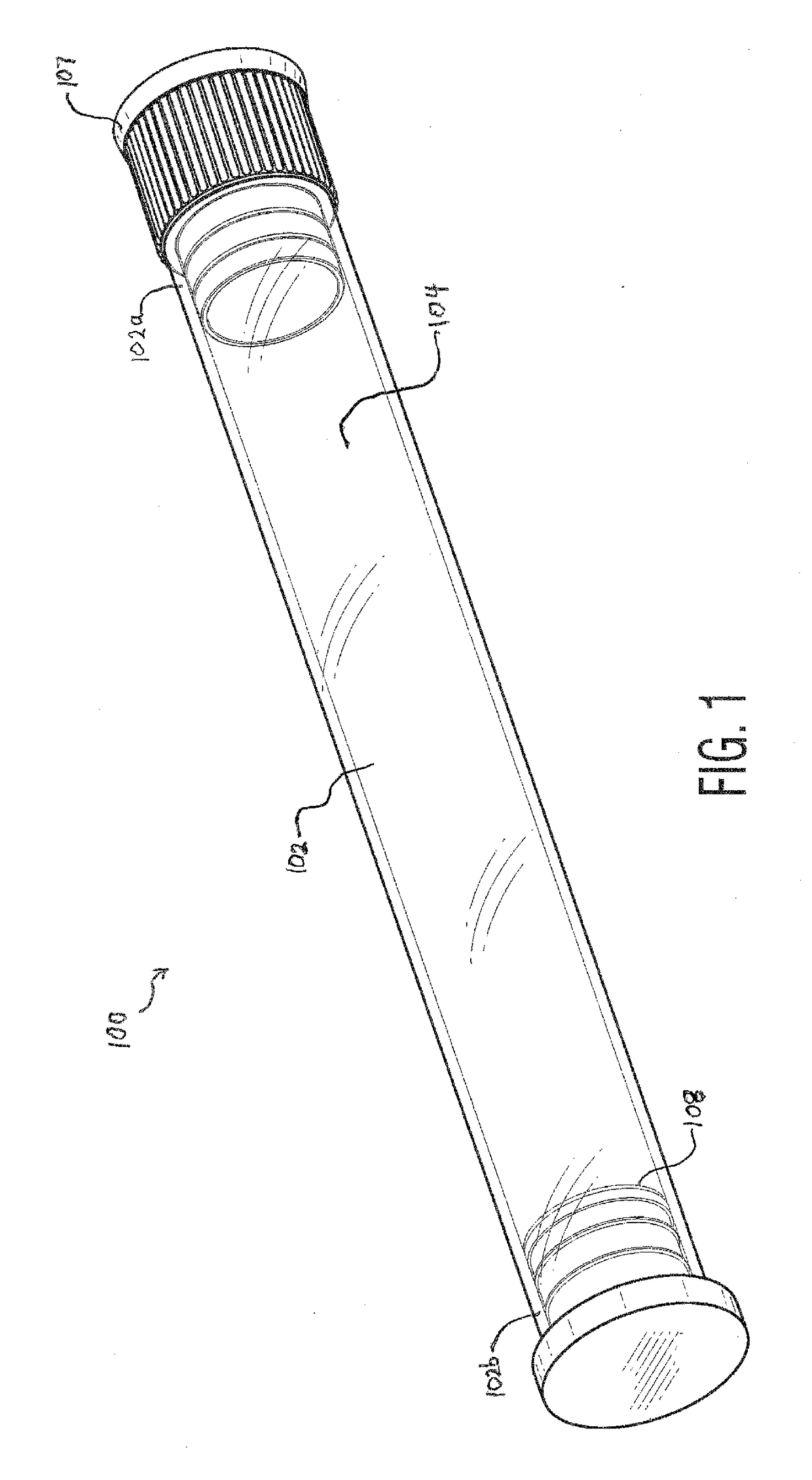
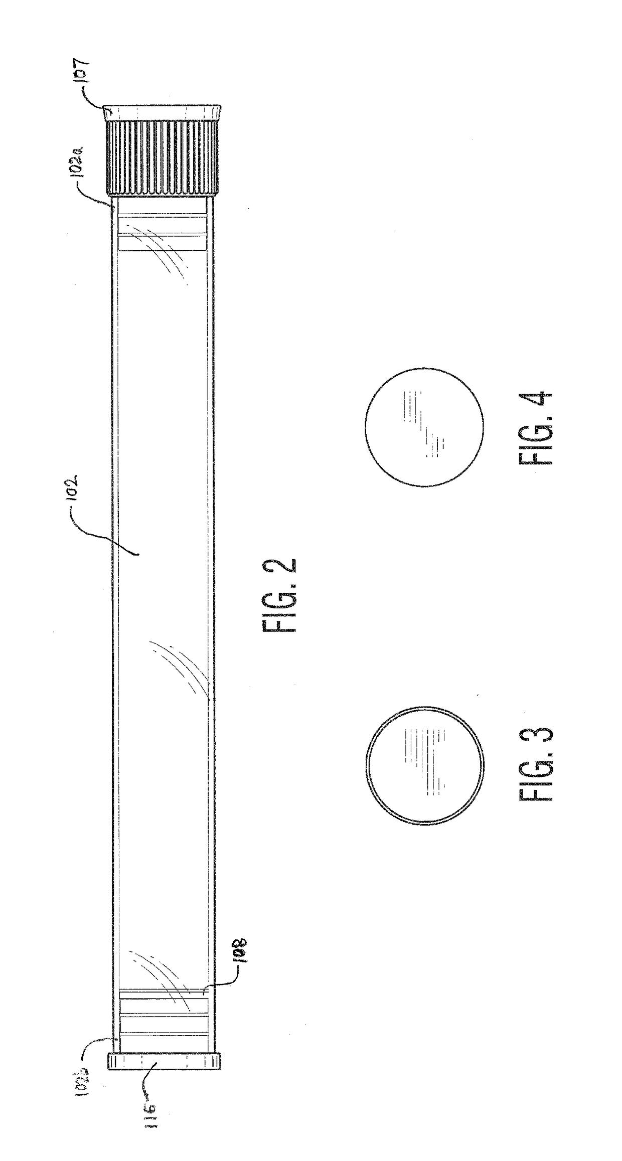
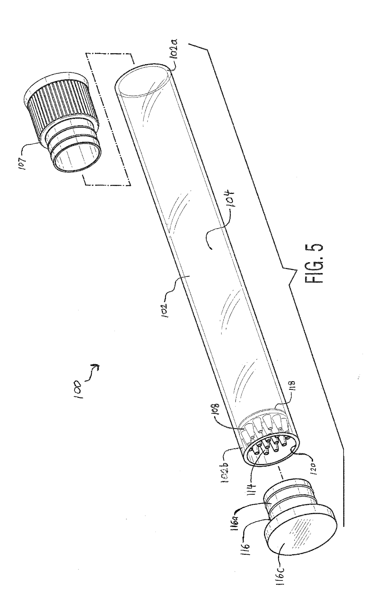
[0080]Persons of ordinary skill in the art will realize that the following disclosure is illustrative only and not in any way limiting. Other embodiments of the disclosure will readily suggest themselves to such skilled persons having the benefit of this disclosure. As previously noted, the device of the present invention is designed to rapidly extinguish a lighted cigar and preserve it for later use. The device is further designed to efficiently collect, contain and dispose of ashes or tobacco strands of a cigar or other smoking article, at the option of the user, and to be carried by the user and to prevent the transfer of undesirable tobacco juices and smoke odors to the user's apparel. In addition, the device is designed to accommodate cigars of different lengths and diameters.

[0081]The present disclosure is generally directed to a cigar tube comprising an elongated tubular member having opposite first and second ends, a top end cap disposed on the first end, an ash collection c...


PUM


Abstract

A cigar tube is provided having an ash catcher and an ash collection cap, for receiving and containing lit or extinguished cigars for later consumption an elongated tubular member having opposite first and second ends and defining a hollow inner cavity disposed between the first and second ends adapted to receive and contain a cigar. The ash catcher is disposed within the inner cavity and has a generally planar body positioned transverse to the tubular member and has a plurality of apertures. A plurality of truncated cones project from the planar body such that each truncated cone preferably aligns with each respective aperture to provide substantially unidirectional ash passageways from the inner cavity to the ash collection cap. In a preferred embodiment, the truncated cones are characterized as having a length sufficient to provide air space between the cones and the ash collection cap for the collection of ashes and dissipation of heat. In one embodiment, a blade is attached to an interior surface of the tubular member and configured to slice longitudinally through an outer sheath of the cigar when inserted through said opening into the inner cavity.

Description

BACKGROUND OF THE INVENTIONField of the Invention[0001]The present invention relates generally to cigars, and more particularly, to a cigar receiving tube, an ash catcher and ash retainer cap for a cigar.Description of the Related Art[0002]It is well known that tobacco leaves are shredded into grinds, flakes, fine shreds or strands which are laid into a binder leaf such as a Havana leaf and rolled into cigar form, often then wrapped with a thin tobacco leaf as the outside wrapper, the sheath, to form a cigar.[0003]Cigar holders have been described in the prior art; however, none of the prior art devices disclose the unique features of the present invention.[0004]Conventional cigar tubes have a number of limitations and disadvantages. Representative examples of them include U.S. Pat. No. 2,047,786, dated Jul. 14, 1936, to Kuntz, in which is disclosed an invention which relates to improvements in cigarette and cigar holders, and has for an object among others the provision of means fo...

Claims


Application Information

Patent Timeline
Patent Type & Authority Applications(United States)
IPC IPC(8): A24F15/18B65D85/12A24F17/00A24B15/28F23Q3/00G09F23/00G09F3/00
CPCA24F15/18B65D85/12A24F17/00G09F2003/0213F23Q3/006G09F23/00G09F3/0291A24B15/282F23Q2/32F23Q2/36F23Q3/01F23Q7/16A24F13/18
Inventor NGUYEN, DANGNGUYEN, THUYLINH
Owner THINGYMAJIGGY LLC
Why Eureka
Try Eureka