Dryer appliance and additive dispensing assembly

Active Publication Date: 2018-12-27
HAIER US APPLIANCE SOLUTIONS INC
View PDF0 Cites 2 Cited by
  • Summary
  • Abstract
  • Description
  • Claims
  • Application Information

AI Technical Summary

Benefits of technology

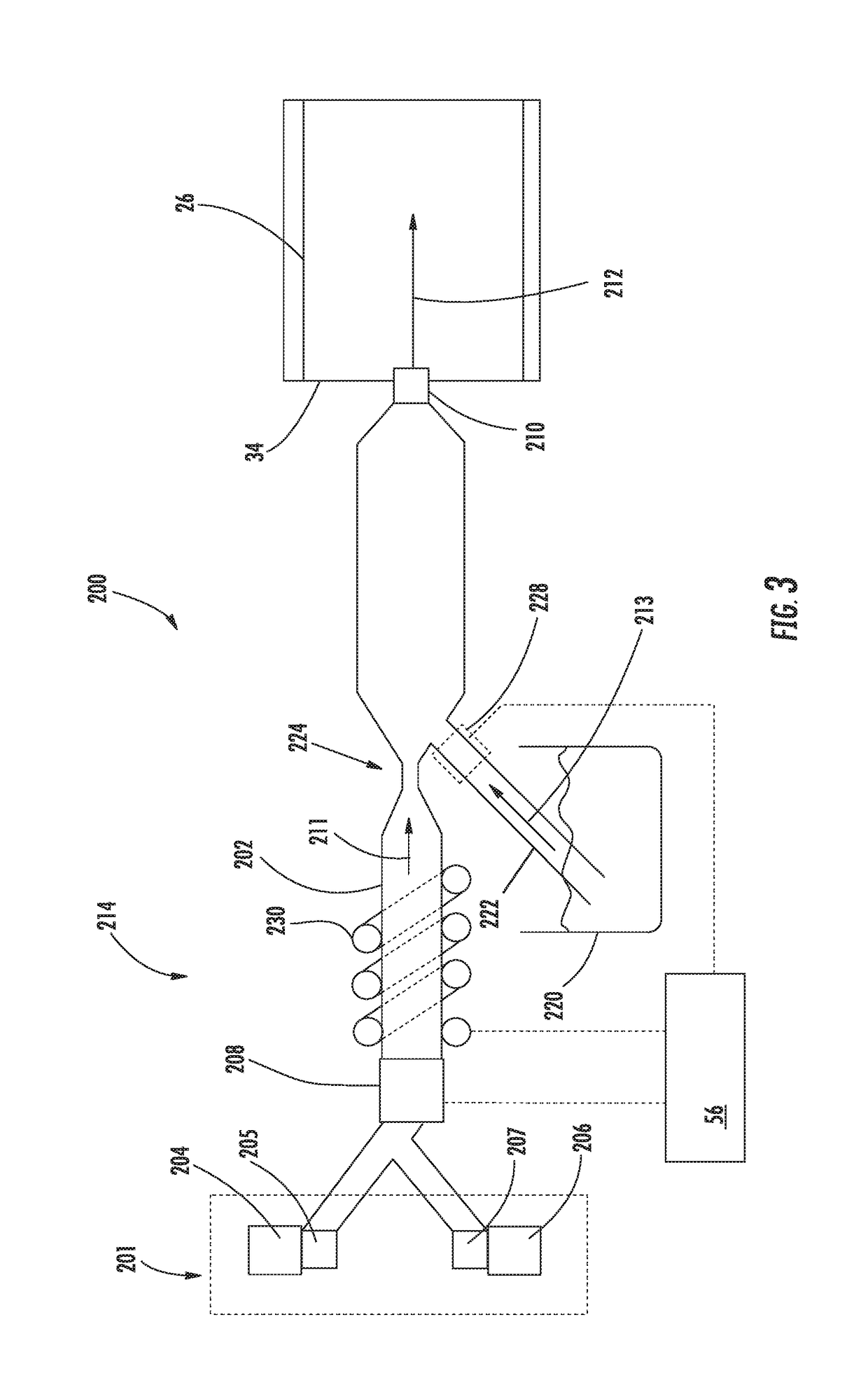
The present invention relates to a dryer appliance with an additive dispensing assembly that provides an additive mist to the drum of the dryer. The additive dispensing assembly includes a supply conduit, an additive dispenser, a siphon channel, and a misting assembly. The initial flow of fluid directed through the supply conduit creates a siphon that draws the dryer additive into the supply conduit to mix with the flow of fluid and create an additive flow. The misting assembly vaporizes the additive flow to the additive mist which is dispensed into the drum. The technical effects of this invention include improving the efficiency and effectiveness of the dryer appliance by reducing the time and energy required for drying clothes, as well as providing a convenient and easy-to-use way to customize the dryer's performance according to the needs of each user.

Problems solved by technology

However, difficulties exist with such approaches.
Although some existing dryer appliances provide for automatically (e.g., without direct user input) supplying steam to individual dryer loads, existing dryer appliances are generally unable to automatically supply specific dryer additives to articles therein.

Method used


Image

  • Dryer appliance and additive dispensing assembly
  • Dryer appliance and additive dispensing assembly
  • Dryer appliance and additive dispensing assembly

Examples


Embodiment Construction

[0015]Reference now will be made in detail to embodiments of the invention, one or more examples of which are illustrated in the drawings. Each example is provided by way of explanation of the invention, not limitation of the invention. In fact, it will be apparent to those skilled in the art that various modifications and variations can be made in the present invention without departing from the scope or spirit of the invention. For instance, features illustrated or described as part of one embodiment can be used with another embodiment to yield a still further embodiment. Thus, it is intended that the present invention covers such modifications and variations as come within the scope of the appended claims and their equivalents.

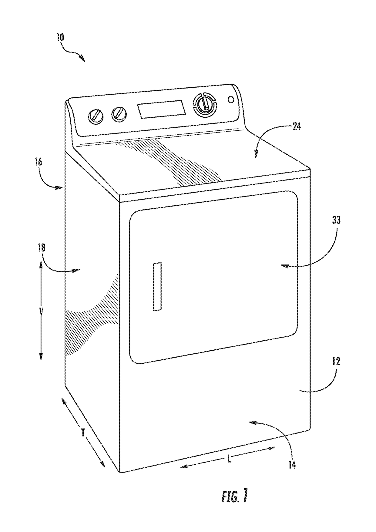
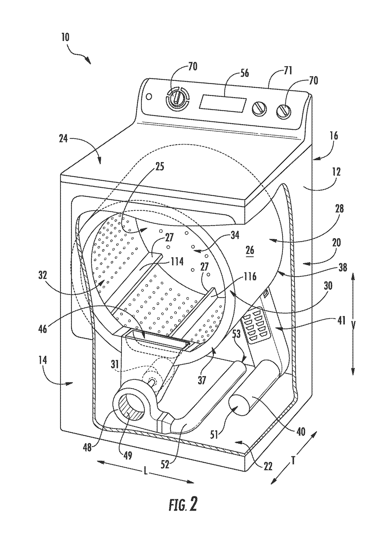
[0016]Turning now to the figures, FIG. 1 provides dryer appliance 10 according to exemplary embodiments of the present disclosure. FIG. 2 provides another perspective view of dryer appliance 10 with a portion of a cabinet or housing 12 of dryer appliance 10...


PUM


Abstract

A dryer appliance and additive dispensing assembly is generally provided herein. The additive dispensing assembly may be positioned within the cabinet and configured to provide an additive mist to the drum. The additive dispensing assembly may include a supply conduit, an additive dispenser, and a siphon channel. The supply conduit may extend between a fluid supply and the drum. The additive dispenser may store and dispense a dryer additive. The siphon channel may extend from the additive dispenser to the supply conduit downstream from the fluid supply. An initial flow of fluid directed through the supply conduit may create a siphon that draws the dryer additive into the supply conduit to mix with the flow of fluid and create an additive flow that is dispensed into the drum.

Description

FIELD OF THE INVENTION[0001]The present subject matter relates generally to dryer appliances, and more particularly to and more particularly to additive dispensers for dryer appliances.BACKGROUND OF THE INVENTION[0002]Dryer appliances generally include a cabinet with a drum mounted therein. In some dryer appliances, a motor rotates the drum during operation of the dryer appliance, e.g., to tumble articles located within a chamber defined by the drum. Dryer appliances also generally include a heater assembly that passes heated air through the chamber of the drum in order to dry moisture-laden articles disposed within the chamber. This internal air then passes from the chamber through a vent duct to an exhaust conduit, through which the air is exhausted from the dryer appliance.[0003]In some instances, it may be desirable to provide certain objects or fluids for the treatment of articles within a dryer appliance. For instance, dryer sheets are commonly placed within the drum of a drye...

Claims


Application Information

Patent Timeline
IPC IPC(8): D06F58/20D06F60/00
CPCD06F58/203D06F2058/2854D06F60/00D06F58/02
Inventor LEIBMAN, ALEXANDER B.
Owner HAIER US APPLIANCE SOLUTIONS INC
Why Eureka
Try Eureka